
| This section is for educational purposes towards the principles of flight and aircraft (or spacecraft) engines / propulsion systems. In this special section, you can see the various principles of flight, types of aircraft and how they work, and details on how aircraft engines, including jet engines, and how those work. This is a must read for any aviation enthusiast. Note - This page may take a while to load on some SLOWER connections! |
Note: This is the section on aircraft flight basics, engines, propulsion systems, and some basic physics involving flight principles. I have a separate section for pictures and such related to flying, and you can click the link provided above to go there.
BASIC AIRCRAFT TYPES
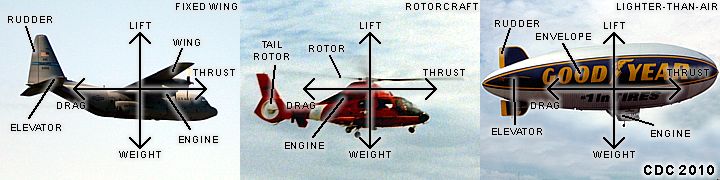
The diagram above shows the three basic types of aircraft - Fixed wing (left), Rotorcraft (center), and lighter-than-air (right). All these aircraft types work on the same basic principles of flight - Lift, thrust, weight, and drag. They differing only by the methods used to generate these forces, mainly lift as the determining factor. Fixed wing aircraft use wings to generate the lifting force to keep the aircraft in the air by countering its weight. Rotorcrafts, such as helicopters, use a rotor to generate such lift. Lighter-than-air aircraft use buoyancy as the lifting force, which can be a light gas (such as Helium) in the case of a blimp (airship), or hot-air as in a hot-air balloon. Forward force, or thrust, is provided by a variety of engines (discussed in detail later in this section). For rotorcraft, the thrust is provided by the lifting rotor itself (which tilts its blades). Thrust (forward force) must match or overcome its opponent, drag, in order for the aircraft to move. For fixed wing aircraft, thrust is essential to maintain enough airspeed so the wings can generate lift to keep the craft airborne. It is the balance of these four forces that affect the way any aircraft flies.
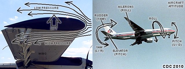
In the diagram above, the details on how an aircraft wing produces lift is shown to the left, and the "degrees of freedom", or aircraft "attitude", is shown to the right. The principle behind a wing is based on the behavior of air (referred to a fluid in physics) and how it flows over the shape of the wing. The general form of a wing is curved on the top surface and flat on the bottom, and is referred to as an "airfoil" and can have many variants. The angle the wing presents itself to the relative wind (has to be moving through the air) is called the angle of attack (pitch attitude). This creates a higher pressure below the wing than on the top, thus forcing the wing (and aircraft attached to it) upwards. The airflow over the wing MUST be at or above what is called a "stall speed", below which the wing cannot generate sufficient lift to keep the weight of the aircraft in the air.
Aircraft attitude (position in space) is extremely important for flight, especially with fixed wing aircraft. The pitch attitude is "nose up" or "nose down" and determines the angle-of-attack for the wings, and therefore dictates lift. The aircraft pitch is controlled by elevators in the tail section of the plane. Side to side motion, called "yaw", is controlled by the rudder of the aircraft, also in the tail. The rudder is in a vertical position, opposed to the elevator, which is horizontal. Finally, roll attitude (moment about the lengthwise axis of the aircraft) is dictated by ailerons in the wings. We also hear of "slats" and "flaps", these are additional components of the wing that allow the wings geometry to be altered, affecting lift (important for a wider speed range, especially on commercial airliners). These aforementioned components are also called "control surfaces". Some fixed-wing aircraft, such as high-speed jet fighters can change the "sweep angle" of their wings to accommodate flight above and below the speed of sound.
For rotorcraft, including helicopters, the rotating blades above the aircraft are driven by the engine, and form what is known as a "rotor disc" as they rotate at high speed. The rotor pushes air downward and each blade on the rotor acts as a wing producing lift. Tilting the rotor disk allows forward and backward motion, or even a hover. The tail rotor allows the rotorcraft to yaw, and also counteracts the torque of the rotor to prevent it from spinning out of control. Finally, lighter-than-air aircraft use a "lifting gas" (such as helium) or hot-air to achieve lift without wings. Control surfaces, as well as thrust vectoring (directing) from the driving engines, provide attitude control for lighter-than-air aircraft. Hot-air balloons, of course, only use lift and weight, and are carried by prevailing winds as there are no engines. Rockets and space vehicles, while in the atmosphere, use similar attitude controls, with the main engines (rockets) overcoming the weight of the vehicle. Once in space, space vehicles no longer "fly" but simply "fall" about a parabolic arc (ballistic). If this "arc" is wide enough (spacecraft has to travel very fast), the craft will continue "falling" and "miss" the earth, which is an orbit.
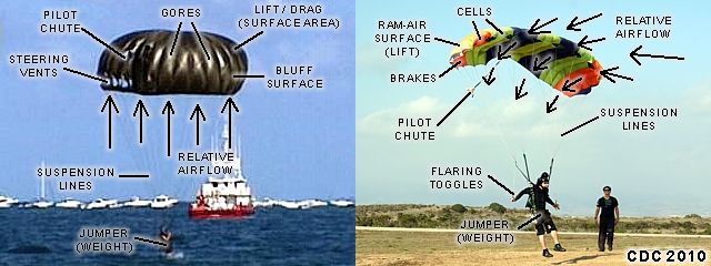
A parachute system is not really a true aircraft; however, it uses many of the important flight principles discussed in this section. The term "parachute" is derived from "break fall" in French. It is an aerodynamic decelerator that works by presenting a large surface area to the relative wind, thus greatly increasing drag and slowing the payload (a person or disabled aircraft) down to a safe speed. Parachutes can be used as a brake (to slow a landing aircraft down) or to slow a falling body to an acceptable speed for landing safely. The round parachute (left in the diagram above) simply works by greatly increasing surface area. A person falling from an airplane (skydiver) may fall at 120 MPH under his / her weight with just his body presented to the relative airflow during the free fall. Opening the parachute increases the surface area (called a bluff surface), slowing the jumper to a mere 10-12 MPH due to drag, allowing him or her to land safely.
To the right in the diagram, we see a ram-air canopy type parachute system. The ram-air canopy is inflated by the relative airflow (entering through "cells") forming a wing shape after it is opened and the jumper is slowed down vertically. The ram-air parachute system is more like a low-performance glider, allowing far more control than its round parachute cousins. Pitch attitude can be adjusted by folding the rear "brakes" of the canopy fabric by pulling down or releasing "toggles". The pitch dictates the lift as well as forward speed of the canopy, allowing far more control, especially when landing. The brakes / toggles also allow the canopy to be turned (yaw), making it highly maneuverable. Parachutes use suspension lines to attach the jumper's harness (or aircraft) to the parachute system. A third kind of aerodynamic decelerator is a combination of a balloon and a parachute, called a "ballute".
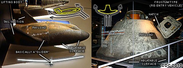
In this diagram, some examples of gliders (or free-falling bodies) are explained. In the image to the left, we see a "lifting body" that resembles a space shuttle silhouette. Below that in an inset, a sailplane glider is also shown. Basically, a lifting body / glider is released from a mother craft (such as another powered airplane) and glides back to the ground under its own weight. There is no engine. The blunt lifting body in the picture is a vehicle designed to re-enter the earth’s atmosphere from space, and glide back to earth to land on a runway after a rapid descent. Thermal protection for re-entry is provided by "ablatable" material, which heats up and vaporizes before the underlying vehicle skin is melted. The sailplane (towed to altitude by another powered aircraft) is designed to have a much lower descent rate, and can go up to 50 feet forward for every vertical foot lost. In both cases, a wing provides the lift (with the lifting body being essentially one large "wing"). In the image to the right, we see a frustum-type (cone section) aero shell. This is designed to simply plummet down into the atmosphere and slow down (aero braking) to a speed and altitude where parachutes are deployed allowing the craft to land (in this case, it's the Apollo re-entry capsule).
PISTON (RECIPROCATING) ENGINES
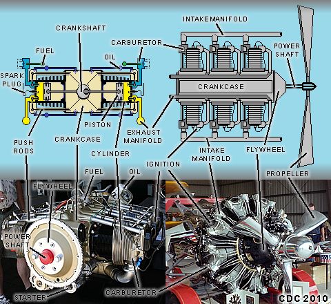
There are many types of aircraft (or even spacecraft) propulsion systems, used to provide thrust in order for the craft to move. The first type is shown in the diagram above and is the internal-combustion engine. This is basically the same engine type you find in the family car. The internal-combustion engine principle works by drawing in air and mixing it with fuel (usually gasoline) and into a cylinder. A piston compresses the fuel air mixture and a spark plug ignites it, causing it to expend rapidly, pushing the piston down. The piston drives a connecting rod to a cam (uneven wheel) which turns a crankshaft (within the crankcase). The momentum of the crankshaft brings the connecting rod (and piston) back around to expel the exhaust gases and repeat the aforementioned process. Valves allow the correct intake and subsequent exhaust strokes to occur in the right sequent, while the ignition system (and timing) fires the spark plugs at the correct point in the cycle. These engines are usually started by a small electric motor (or even a spring) to get the crankshaft moving.
Often multiple cylinders and pistons are connected to a crank shaft to turn it and provide power. A flywheel at the front of the crank shaft connects the engine via a coupling (power-take off or PTO) to a drive shaft and propeller. A propeller is a bladed device which rotates much like a helicopter rotor, using its wing-shaped blades to force air (or any fluid) back and create forward thrust. In the images above, a partially cut propeller can be seen to the lower right, with the wing-shape of its cross section clearly visible. Aero internal-combustion (piston) type engines are also called "reciprocating" engines (piston moves "back-and-forth"). Many of these engines are air-cooled, using cooling fins on each cylinder and the engine oil being essential as both the coolant and lubricant. The engine to the left is a 260 HP six cylinder "opposed" or "flat" engine, while the engine on the right is a 2,500 HP 9-cylinder "radial" engine. Reciprocating engines are relatively inexpensive and fuel efficient, and are used on many modern aircraft.
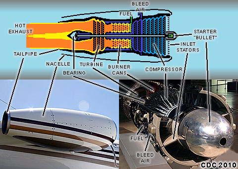
In this area we will look at several types of "gas turbine" engines, starting with the simplest of them, the "turbojet" engine. Gas turbines work by a continuous combustion cycle, apart from the reciprocating engine above. Air is drawn into a fan-like compressor disks in the front of the engine. These disks are curved, wing-like blades about a central rotor shaft. Multiple compressor wheels care called "stages". Finally, the incoming air is compressed and becomes very hot. This is then fed into the combustion section of the engine, where it mixes with fuel (usually a light oil or jet fuel, such as kerosene) and ignites. The hot expanding gases then leave the combustors through a turbine wheel, which is attached to the same shaft that drives the compressors. There is usually one shaft (or "N1 spool") to which the turbines and compressors are optimized to run on at speed, which can be at least 20,000 RPM. More complex turbojets may have two shafts, or "spools", called N1 and N2. About two thirds of the total power produced by the engine runs the compressor stages, with the leftover "energy" as hot exhaust continuing to the rear of the engine through a tailpipe / nozzle assembly at tremendous speeds. The combustion chambers are designed so air entering them "holds" the hot flame away from the walls of the chambers, so they won't melt.
Since a volume of air was drawn into the engine, accelerated to high speed and ejected from the rear of the engine, the inertia (refusal to accelerate a mass) of that air creates a reaction force in the opposite direction (Newton's law). This "reaction" force, like letting air out of a party balloon, provides forward thrust, driving the engine (and aircraft) forward. The tailpipe "nozzle" is crucial to accelerating the exhaust gases and creating such thrust. Without such a nozzle, the turbojet can be called a "gas generator". The inventor of this type of engine was Englishman Frank Whittle back in 1937. In the diagram above, a simple turbojet is shown. The engine is started by an electric motor (or in some cases, compressed air) that brings the rotor up to speed, where a spark plug system initially ignites the fuel-air mixture in the combustors. Bleed air, used for aircraft accessories and air conditioning, my be drawn off the compressor. Other accessories not shown involve generators for electric power from the engine. A turbojet is very loud and poor in fuel efficiency, as much of the useful kinetic energy of the exhaust is wasted as heat and escapes through the tail-pipe. Many vintage military aircraft were powered by turbojets, and many produce thrust on the order of several thousand pounds.
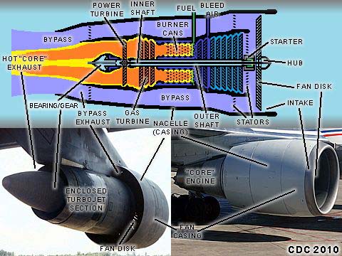
With efficiency in mind, the "turbofan" engine is basically an enclosed turbojet engine (or "gas generator") utilizing the high-speed (and hot) exhaust of the enclosed engine (or "core" engine) to drive a large ducted fan in the front of the engine. The design of the enclosed "core" turbojet / gas generator engine is very similar to the example for the turbojet above, so here we'll focus on the differences. The high-velocity (and noisy) turbojet exhaust is basically a waste of kinetic energy, so in the turbofan engine, it powers an additional set of turbine blades, called a "power turbine". A separate shaft (usually around the core engine "N1" shaft, and called the "N2 spool") drives the large fan in front of the engine. This second "N2" shaft has its own set of power (or "low pressure") turbine stage(s) and is optimized to turn the fan in front of the engine. Sometimes a reduction gear optimizes the high-speed power turbine with the lower speed requirements of the fan, which spools (turns) at about 3,000 RPM. The "spent" hot exhaust rushes back through the turbojet's exhaust and meets the larger cool "bypass" air jacket from the fan. The bypass air flows around the core engine, and is ejected rearward at high speed. The enclosed turbojet exhaust is also much cooler and slower than the turbojet alone.
Turbofan engines (sometimes called "fanjets") are status-quo for nearly all modern commercial airliners. They are very powerful, quieter, and far more fuel efficient than their older turbojet predecessors. The same principle of drawing air in, accelerating it to high speed, and ejecting it through a nozzle applies (just a larger mass of air), causing thrust (reaction force) due to Newton's law. The engine is also started by a motor or compressed air to spin (or "spool") the engine to speed before ignition of the fuel-air can be sustained. There are different sizes and shapes of turbofan engines, mainly dictated by the "bypass ratio", which is how much air is directed by the fan and not through the enclosed turbojet core. Low bypass engines may route only a small volume of air (50% or less) as bypass air (such as a JT-8 D engine on a Boeing 727), while high bypass engines route 85% (or more) as with a Boeing 747 (using GE CF-6 engines). Most use the two spool design (2 shafts), but a few, such as those manufactured by Rolls Royce (including the RB-211), can have 3 concentric shafts for rotating components - With a high-pressure N3, "intermediate" N2 spool, and fan / low pressure N1 system. The examples shown above in the lower part of the diagram are high-bypass turbofans. Typical thrust of such engines can be upwards to over 50,000 pounds of thrust.
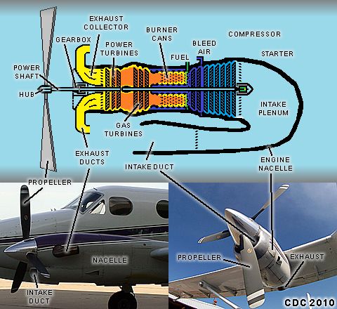
Instead of a piston / reciprocating engine driving a propeller, why not have a gas turbine do it? That's the concept behind the "turboprop" engine (also called a "propjet"). Again, as you can see in the diagram above, the engine is an enclosed turbojet "core / gas generator" engine, but instead of driving a large fan, the extra set of turbine blades drive a propeller. With the turboprop engine, the enclosed turbojet / gas generator provides the compression, combustion, and exhaust duties. The hot and fast exhaust is then routed through the "free" power turbines, which drive the propeller shaft through a reduction gear set, separate from the turbojet. Propellers cannot be turned at high speeds (more than 2,500 RPM because the tips of them may exceed the speed of sound, creating "wave" drag, vibration, and noise). The power turbine assembly can be either on an enclosed shaft, or "free turbine" shaft, as shown in the diagram above. The "spent" exhaust, with much of its kinetic energy transferred into the power turbines driving the propeller, escapes via an exhaust collector and ducts. The engine is started the same way as the turbojet (via a starter motor or compressed air), where the engine is "spooled" up to allow fuel-air ignition.
Turboprop engines are a compromise between the high-speed of turbofans / turbojets and the lower speed propeller-driven aircraft needs. They are also fuel efficient (but not as much as the reciprocating) and provide reliable power to most modern general, utility, and regional commercial aircraft (such as the King Air PT-6 engine shown in the lower left of the diagram above). Variants may include "reverse flow", also shown in the diagram, where air enters a scoop and enters the rear of the engine casing, or nacelle (as with a PT6-A turboprop) with exhaust exiting through side ducts. To the lower right, a Garrett turboprop uses an axial-flow (front to back) to power a Shorts Skyvan. Some turboprop engines have a "free" power turbine, completely separate from the gas generator, as in the PT-6, designed to turn the prop (usually a gearbox). Others, such as the Garret powering the Skyvan, have a single shaft on the gas generator spool connected directly to a reduction gearbox turning the propeller. Turboprop engines usually generate anywhere from 500 to 1,500 horsepower (and up).
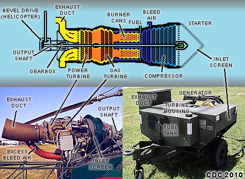
Finally, and yet another modification of the gas turbine / turbojet engine can be looked at. This is simply called a "turboshaft" engine, where a work-load of some sort is used in the same manner a propeller would be as with the turboprop example in the previous section above. With a turboshaft engine, a gas turbine (enclosed turbojet / gas generator) turns additional power turbines in the same manner as with the turboprop. Instead of turning a propeller, the power turbine shaft is "matched" with the work-load via a reduction gear and based on the application involved. In the diagram, and in the image to the lower-left, a turboshaft engine is being used to power a helicopter (it's an Alhouette helicopter powered by a 400 HP TurboMecca engine in the picture). The same setup can also be used for power generation (especially in industrial applications), where an electric generator is powered by the gas turbine. Such a case of power generation via turboshaft is the fully-contained 25 KW free-turbine ground power unit (or GPU) in the image to the lower-right. Other applications can range from ship propulsion to pipeline compressor / pumping stations.
With the basics of jet engines now under our belts, let's take a look on how a jet engine is modified to allow very high-speed flight. The speed of sound is roughly 750 MPH near sea-level on a standard day (about 15 deg C at sea level in dry air). The speed of sound changes with conditions (much slower higher up, and only 660 MPH at 40,000 feet). Since this speed changes, a "Mach number" is used, with Mach (or "M") 1.0 being the speed of sound. Speeds below Mach 1.0, usually from 0.8 and under, are said to be "subsonic". Above Mach 1.0, usually from 1.05 and up, are called "supersonic". Speeds "around" Mach 1.0 (say from 0.8 through 1.05) are "transonic" and depend on the shape of aircraft, types, and such. One key factor that Mach number has to do with jet engines is the effects of "shock waves" and "compressibility" that develops at or above the transonic regimes. When shock waves develop, they create air disruption, drag (called "wave drag"), and lots of heat. This is NOT something you want in the air inlet and compressor "face" of a turbojet (or turbofan).
In order to allow a jet engine to continue running in airflow faster than sound, the air must first be slowed down BEFORE it reaches the intake of the engine. A properly designed air inlet is essential to this duty. On many supersonic aircraft, ranging from jet fighters to the SST (Concorde / Tupolev), the air inlets for the jets are prominent, with interesting geometry and / or angled surfaces. In the example above, and to the lower-right, the inlet of an F-15 Eagle fighter jet is shown. When the aircraft flies faster than sound, the inlet is designed so that shock waves form and slow down the air before entering the jet engine, via moveable surfaces or "ramps". Any excess air can also be "dumped" from the inlet through trap "doors". Much of this is carried out by an onboard flight computer, compensating for air density, Mach number, and such. Finally, the supersonic flow is slowed to subsonic speed, at a higher temperature and pressure, and can enter the compressor of the turbojet / turbofan engine. At speeds above Mach 2.5, heat becomes a big problem, and the engine can melt, so inlet design is even more challenging (aka "Thermal Barrier").
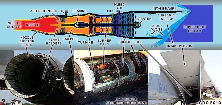
In addition to the proper inlet design, the engine itself needs to produce more power (thrust) to overcome the increased drag (and wave drag) as the aircraft reaches transonic (and supersonic) speeds. One solution is by adding an "afterburner" assembly (also called "post combustion") to the rear of the turbojet / turbofan tail-pipe. The jet engine is shown in the middle image in the diagram above, and is basically a normal jet engine. The afterburner is a secondary combustor where fuel is sprayed into the hot exhaust stream of the turbojet (or core engine) and nearly doubles the thrust of the engine. This extremely hot and high-speed exhaust escapes through a nozzle and increases the overall pressure-ratio (more reaction force = more thrust) of the engine. Bypass / bleed air is used to keep the afterburner flame from touching the walls of the afterburner "can" and nozzle, so they won't melt. Ejector flaps allow the nozzle of the engine to be altered to optimize the speed of the exhaust stream. Such devices can be seen in the image of an afterburning nozzle of an F-15 Eagle to the lower-left. Such engines can produce over 25,000 pounds of thrust, but are no way fuel efficient (and loud) when using afterburners. Supersonic flight without an afterburner is called "super cruise".
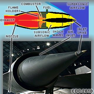
Aside from gas turbine / conventional jet engines, there is the simplest design of any jet engine, the "ramjet". This jet engine is basically a fancy "pipe" shaped in a sense to allow air to rush (or "ram") into the front of the engine, mix with fuel and burn, and rush out the tail-pipe, driving the engine forward (thrust) through reaction. The engine has little or no moving parts; however, one major aspect is that the ramjet must first be brought up to an "operating" speed range in order for it to work. Most ramjets will not operate below supersonic speeds, and high Mach numbers, such as 2.5, and higher, are required. In the diagram above, air enters the inlet of the engine, which is specially designed to slow down the air (to subsonic or slower supersonic speeds, as with a supersonic-combusting ramjet / SCRAMJET). This heats up the inlet (shocked) air where it enters the combustor and burns with fuel. The extremely high-speed exhaust rushes back through the tail pipe, there are no turbines or rotating components.
Ramjets often power very high-speed air vehicles, designed to travel at high supersonic or even "hypersonic" (Mach number at or above 5.0) speeds. These are often experimental (X Planes), missiles, or conceptual (not yet implemented) aircraft. Some other engine, usually a rocket, is used to bring the ramjet package up to operating speed. They are not fuel efficient. In the diagram above, the engine inlet of a "turbo ramjet" engine is shown on an SR-71 Blackbird in the lower image. In this case, it is a combined ramjet and turbojet engine (with afterburner). Above Mach 2.5, achieved by the afterburning turbojet, the moveable air inlet "spike" sets the air intake (slowing and heating the 900+ deg F shocked supersonic flow) so that the air no longer passes through the turbojet, and directly into the afterburner, forming a ramjet. This allows the aircraft to accelerate to nearly Mach 3.5, faster than a military rifle bullet, and above 80,000 feet! Heat, again, becomes the limiting factor in such materials and limits speeds to more like Mach 3.0.
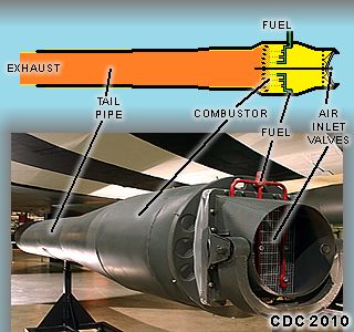
A "pulsejet" is another type of engine with only a few moving parts, basically at the inlet of the engine. They are also called "aero resonator" engines because they are extremely loud. They also powered German V1 "buzz bomb" unmanned vehicles during World War II. The engine cycle works by first drawing air into the front of the engine, when inside the chamber (or combustor); fuel mixes with the air and is ignited. This expands as it burns, with the exhaust ejecting out the back (tail pipe) of the engine, while forcing the inlet "doors" at the front of the engine shut. When the exhaust cycle is complete, the air inlet valve doors swing open, and the cycle repeats, up to 30 times, or more, per second. The engine is usually started by an "initiating" blast of air into the front of the engine and spark ignition, after which, the pulse-combustion is sustained. Another jet engine (or rocket) can also be used to launch the vehicle (and pulsejet package) and it can be started in the air once airflow is established at the pulsejet inlet.
In the example above, the schematic on a pulsejet is shown, with an actual unit on display below it at the Wright Patterson Air Force Museum near Dayton, Ohio. There are also "valve less" pulsejets which use sonic waves to "start" and "stop" the airflow into the engine inlet instead of "doors", as stress on the inlet often causes the pulsejets with valves to fail. Pulsejets are now mostly experimental by hobbyists/ demonstrators. They are not fuel efficient, run red (or even white) hot, and create an ear shattering noise.
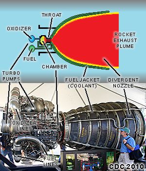
Before this point, we discussed principles of flight and engines to provide power for aircraft. Until this point, all the aforementioned engines were called "air breathing" engines, meaning they require air (oxygen) and an atmosphere to function. In this section, "Rocket" engines do not require air to function, and need to use an on-board oxidizer in addition to fuel. Rockets have an extremely high power to mass ratio (a lot of thrust in a "small" package), but are very inefficient fuel-wise. The ability to operate without air makes them ideal for spacecraft; however, they have been used on a variety of aircraft as well. Besides the space shuttle and other spacecraft, liquid fuel rockets have powered the German ME-163 Komet, and have been used for rocket-assisted takeoff (RATO) for heavy cargo planes. In the diagram above, a main engine from the Space Shuttle is shown in the bottom image, with a simple schematic of a rocket engine above.
Basically, fuel and oxidizer are mixed in a reaction chamber, react violently creating an expanding exhaust, and escape through a rocket (usually a "Laval" convergent-divergent bell-shaped) nozzle creating forward thrust (due to reaction forces). There are two basic types of rockets, solid fuel (solid fuel and oxidizer are mixed together in a package), and liquid fuel (which is easily controlled or "throttled") as in the example above. There are also other types of rockets, such as nuclear and ion propulsion, but that's not discussed here. For a liquid cooled rocket, the fuel can be circulated through tubes in the nozzle to cool it and pre-heat the fuel. High pressure pumps provide the reaction chamber with fuel and oxidizer, with a spark igniting it if necessary. Solid rockets cannot be stopped once they are started, as the fuel and oxidizer are contained in the unit until used up. Rockets can range from less than a pound of thrust (as in model rocketry), to well over 3 MILLION pounds, as with the Space Shuttle!
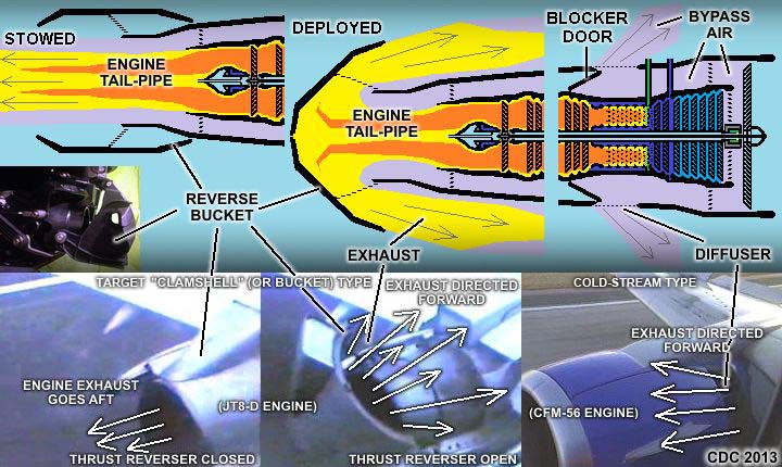
Have you ever been on a commercial airliner and the jet engines appear to spool up as you are slowing down? This is because the engines ARE being used for braking. Thrust reversal is available on most aircraft jet engines, and there are two main types. One is called the "target" reverser, and uses a reverse "bucket" or "clam shell" type apparatus. Another uses a system of "blocking" doors and directs the air (usually bypass air) forward, and is called the "cold-stream" type. The latter can usually be found on higher bypass jet engines. Both methods work basically the same: Air enters the engine and is burnt with the fuel to produce power and a hot exhaust stream and cool (bypass) air jacket (from the large fan). If this exhaust is directed forward, instead of rushing out the rear of the engine, you should have a reaction force (retro-thrust) that can slow the aircraft down, or even cause it to go backwards (such as in a "power-back" from an airport gate). In the diagram above, the left two pictures show the reverse "bucket / target" type system - In the normal (closed or "stowed") position, where the plane is pushed forwards, as well as the "deployed" (open) position to produce reverse thrust. The un-deployed reverse "bucket" simply forms the rear casing of the engine nacelle when it’s not in use.
In the inset, the rear view of a personal watercraft, also powered by a very similar "reaction" force water jet, also has a reverse "bucket" type apparatus. In the images to the far right, a cold-stream type thrust reverser is shown. These are found on the higher bypass engines (where the former target / bucket type is used on lower bypass engines and turbojets). The larger mass of air from the fan bypass is more than enough to slow the aircraft down if directed forward. A "blocker" door (or dump / spill mechanism) closes and directs the bypass air jacket forward through a grating, and creates reverse thrust. The air is usually directed forward at a 60 degree angle to minimize the possibility of kicking up debris, which could damage the engine if it enters the inlet. Although not shown here, turboprop (and many propeller) driven aircraft also have reverse thrust, but it is accomplished by changing the pitch of the propeller so it drives air forward instead of aft, slowing the aircraft, and is sometimes called "propeller discing". Rocket (as well as pulse / ramjet) engines do not have thrust reversing capabilities; however, a (retro) rocket pointing forward can also provide reverse thrust (but is independent from the main rocket engines).
SUBSONIC FLIGHT (UP TO THE SPEED OF SOUND)
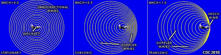
In the diagram above we can see three stages of subsonic flight - Stationary (left), "subsonic" near Mach 0.5 (center) at half the speed of sound, and "transonic" near Mach 1.0 (right). With a stationary object (very slow or not moving), any sound and / or pressure disturbances radiate outward evenly in all directions in still air. Once the object begins moving, it creates both sound and pressure disturbances, and these waves are left behind as the object producing them speeds up. At roughly half the speed of sound, the pressure / sound waves only make it half way ahead of the object's direction of travel, while behind it, they become more stretched out. This is called a "Doppler effect", and an example of this is that familiar pitch change of a train horn passing a stationary observer. At such speeds, the pressure / sound waves can still make their way away from the object (or aircraft) at subsonic speeds. When the object (such as an aircraft) reaches the speed of sound, Mach 1.0, the pressure and sound waves cannot get ahead of the object, and only escape behind it. A small shock wave forms at the front of the object (such as the aircraft wings and nose) as the pressure waves are essentially trapped there (compressibility). Wave drag (drag caused by shock waves) also begins at transonic speeds.
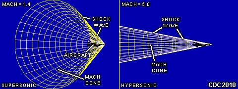
In the diagram above we can see two examples of "supersonic" flight, which is above the speed of sound (or Mach 1.0) - "Supersonic" at Mach 1.5 (left), and "hypersonic" near Mach 5.0 (right). When an object travels faster than sound (above Mach 1.0), it is said to be supersonic, and no sound or pressure waves can get ahead of it. Very much like the bow wave left behind a moving boat, the sound and pressure disturbances form a sharp shock wave, that radiates outward in a conical shape behind the object. The angle of this cone relative to the centerline of the object's path is related to the Mach number. Any object traveling faster than sound encounters wave drag or even controllability issues (such as "Mach tuck") caused by the shock waves. Swept wings and pointed fuselage shapes, known as "Sears Haack" bodies are essential to minimize the wave drag. Behind the main shock wave, air slows to subsonic speed near the object, in that is called a "shocked layer".
A stationary observer may hear (and feel) a sonic boom (loud bang) when the shock wave reaches him (or her). At speeds at or above Mach 5.0 (hypersonic), drag still increases, but friction also generates a lot of heat. This heat (or thermal rise) usually limits sustained hypersonic flight because aircraft components and engines can melt from it. At high hypersonic speeds, such as re-entry of spacecraft, the shocked layer becomes so hot it turns into a plasma. Ablatable materials or thermal protection (such as tiles) are then essential.
HTML File "aeroeng.htm" - Developed By Chris Collura
To Return To The HOME Page Of This Site Click The "INDEX.HTM" Link Here!