
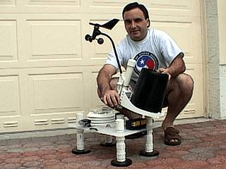
| This area shows the construction and completion of yet another prototype of a portable weather station. This third unit, dubbed "Weatherlab III", is a super-improved and lighter version compared to the original two prototypes. The unit boasts a Davis WIRELESS Vantage Pro weather station and completely re-designed structure. The main "deck" of this weather station is a solid 13x17 inch polycarbonate cutting board, so there is no more PVC frame to assemble. The main equipment is built onto, and even "into" this strong, hail-proof deck. Even he four mounting magnets were re-designed to be screwed into each corner. The wind and rain measuring devices wan also be mounted and dis-mounted via 2 quick RJ-12 jacks and a single wing-nut bolt.
All the weather instrumentation is completely self-contained, solar-powered, and wireless! Optional power and audio connections are still provided for the new lights and flashing strobes on the unit via a re-designed SINGLE quick-connect control box and cabling. The whole goal here is weight savings and simplicity in bot set-up and operation. The entire unit can fit in a regular suitcase, weighs less that 40 pounds, and can be set up in less than 15 minutes on any vehicle! You can even place the weather station anywhere and it will transmit information to the hand-held Davis weather computer up to 400 feet away. This unit can travel anywhere in the world for storm chasing operations. Check out the pictures and construction of the "Weatherlab III" unit on this page! Note - This page may take a while to load on some SLOWER connections! |
|
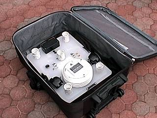
The main features of the new Weatherlab III weather station are portability, ease of setup, and light weight / volume during transport. In this picture, the entire weather station, less the anemometor and rain guage, easily fits within an average suitcase with plenty of room to spare. The entire station can be packed away, using clothes as a "cushioning medium", in such a suitcase instead of the heavy, bulky transport chest used inb previous prototypes "Weatherlab I" and "Weatherlab II". |
|
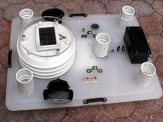
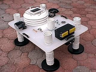
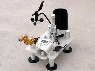
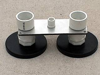
This is a picture of the top side of the "base" unit of the Weartherlab III station. In each corner, is a mount for ant extra equipment. The solar panel and temperature / dewpoint sensors are housed in the round, louvered casing to the left. The center mount is for the anemometer and rain-guage mast while other connectors are for optional power and communication (antenna) requirements. To the right, is a large black box which houses the driver circuitry for the flashing yellow strobes in the rear of the unit. Two side-pointing headlamps can also be seen in this picture. The base unit is actually a 13x17 inch polycarbonate chef's cutting board at 5/8 of an inch thickness, able to withstand "attacks" by giant hail. The two RJ-12 jacks (lower-central portion of the picture) connect the anemometer and rain-guage sensors to be quick-connected. |
|
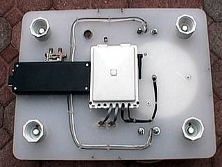
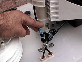
Here is a view of the bottom of the Weatherlab III base. In each corner, there are four mounts for the screw-in PVC magnet mounts (constructed out of 1 1/4" schedule 40 PVC). To the left is a black box housing electrical connections. In the center is the "brain" of the Davis Vantage Pro weather station. This white box ties all components together and has a small antenna for transmitting the information to a hand-held computer (via the small antenna on the upper right-side of the white box). The insulated wires on the top and bottom of the picture are for the headlights. Also note the antenna connections (BNC type) just above the white box and lightning arrestor (required for "storm-chasing" operations). |
|
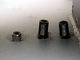
This weather station is designed to be mounted atop four magnet mounts. In this picture, each mount is simply screwed into place to set the mount points. |
|
In some cases, the magnet-mounts may require an "extension". The extension is simply a screwable PVC coupler about 6 inches long if more "clearance" beneath the mounted weather station is required. |
|
This is the Weatherlab III weather station with extended magnet-mounts installed and ready to place atop a chase vehicle. To this point, setup was a mere 5 minutes! |
|
Here is a picture of the rain-guage and anemometer assembly. These two sensors are attached to a single 1 1/4" PVC mast that connects to the weather station with a simple bolt and two RJ-12 connectors. In this picture, the rain-guage and anemometer are attached to the PVC mast and ready to mount atop the Weatherlab III station. You can also configure these sensors as required, for example, only the anemometer will be used on some chases, while others only require the rain-guage. |
|
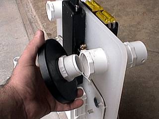
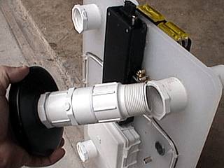
Here is a close-up of the "mount-point" of the rain-guage and anemometer assembly. My index finger is pointing to a single wing-nut and bolt securing the unit while the two RJ12 connectors can be seen in the lower portion of the picture. Why such ease in connectivity? Suppose a hail-storm is bearing down on the vehicle using Weatherlab III. One needs to quickly remove the wing-nut and bolt, unhook the connectors, and take down the most-delicate (to hail and debris) anemometor / rain-guage, all in less than 30 seconds! |
|
Here is a picture of the Weatherlab III weather station with the anemometer and rain-quage being installed via the "quick-connect" bolt, wingnut, and RJ-12 connections described above.. |
|
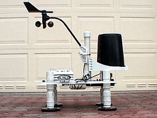
This is a picture of the Weatherlab III portable wireless weather station sporting its entire suite of weather sensors. The temperature, pressure, dewpoint, wind direction, anemometer, and rain-guage sensors are actually operating in this picture. |
|
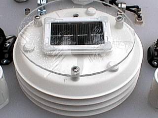
In this picture, the radiation-shield for the temperature / dewpoint sensor can be seen. It is housed in the white high-impact round louvered plastic enclosure. Atop these sensors, the power cell for the unit, a solar cell, is housed and protected beneath a 1/4 " plexiglass (bullet-proof, and most likely "hail proof") hard-hat. |
|
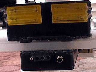
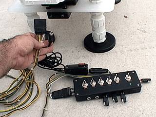
The Weatherlab III weather station was also designed to allow 12 VDC car power to be supplied to less-essential and optional units on the weather station. In this picture, a 4-pole trailer power connector mates the 12 VDC components, such as the head-lights and yellow strobes (seen here) with a controller unit operated from within the vehicle. The single connection eliminates the drudgery of running multiple wires and provides set-up simplicity. The strobes are alternate flashing yellow whose controller circuits are sealed in the water-proof black plastic box in the top of picture. |
|
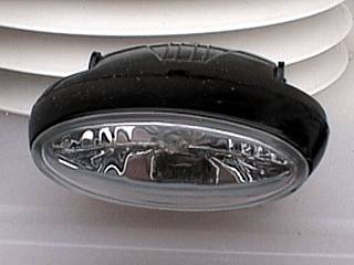
Here is a picture of one of the two side-looking head lights for the Weatherlab III unit. Each light draws only 3 amps at 12 VDC but provides optional side illumination from the top of the vehicle using the setup. |
|
An additional two 12 VDC power outlets plus and RCA jack were provided in case extra 12 VDC equipment is to be mounted atop the Weatherlab III station. The 12 VDC connectors are controlled by a single switch on the controller unit and are 2-pole trailer connectors glued into the unit deck. The RCA jack is a pass-through to another RCA jack near the 4-pole trailer connector and allows an audio device to also be installed (such as a speaker). |
|
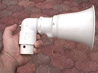
This is a picture of a "bull-horn" type speaker that is to be used with the new Weatherlab III station. It is the speaker unit from a musical Powerhorn (Radio Shack) painted white and attached to a PVC mount. The connector is a simple RCA jack and is next to my thumb to the left. The speaker is installed via a single wing-nut and bolt and connected via RCA jacks and cables, and can produce at least 113 dB at 1 Watt / meter. The speaker is to be used as a siren / hailer feature. |
|
Here is another picture of the Weatherlab III weather station set up and ready to install atop a vehicle. Note the speaker and camera attachments in the front of the unit. All weather instrumentation is operating and transmitting data in this picture. |
|
This is a separate magnet mount using the same type of connectors and two screw-on magnets as the four used in the weather station. This mount is used for separate antenna, instrument, or camera requirements and is both independant and optional from the rest of the equipment. |
|
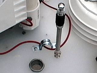
The Weatherlab III base unit also has an integral BNC mount for a HAM radio (2m) / FM and weather-band radio. The antenna can be seen cleanly mounted to the BNC connector. On the bottom of the deck, an RF cable can be used to connect the antenna using the same common BNC connector. A lightning arrestor is also included with this unit (not visible in this picture). Also note the 1" pass-thru hole and half-circle mount for securing optional wiring (in this picture a red RCA cable runs through it). |
|
Here is a picture of the control module for the Weatherlab III unit. This is the same control box used for the Weatherlab II, modified so that the first three switches (the next three after main power) power 3 of the poles (the 4th being the common ground) in the 4-pole trailer plug (added to the control box to the left of it). The switches operate the head-lights, yellow strobe, and 2 power connectors, respectively. The cable runs into another smaller box with a switch on it via the same 4-pole connectors. Out of this small box (above the large control box in this picture) runs a 20-foot cable bundle to mate with the 4-pole trailer connector on the back of the Weatherlab III unit. Also note that a long RCA cable connects the small box with the back of the Weatherlab III connector. This is for an audible siren, also contained in the smaller black box, and controlled by the single switch on that smaller box. The siren is only available when the third switch on the control box (the power for the two auxiliary outlets on the station) is energized. |
|
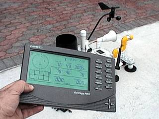
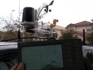
This picture shows the Davis Vantage Pro hand-held weather computer console in the foreground receiving wireless data from the Weatherlab III station behind it. Note that there are no wires and the weather station is a separate, solar-powered, independant unit. Transmitting range is up to 400 feet line of site. In this picture, the temperature is 76 Farenheit with a humidity of 43%, barometer at 30.05", 0.00" rain, and a N wind of 1 MPH. Units are fully adjustable between metric and standard scales too. |
|
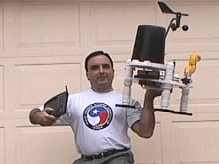
This picture illustrates the size and light-weight of the entire Weatherlab III system. In my left hand, I am holding the entire station with all the extras, and in the left, the computer console. Remember, the goal here is respecting reliability, simplicity, and weight. The unit is functioning as this picture was taken. |
|
Here is the Weatherlab III station atop a vehicle (background) still functioning as a stand-alone unit via solar power (or internal batteries if no sun) with a fully populated display of weather data on its weather computer console in the foreground. |
|
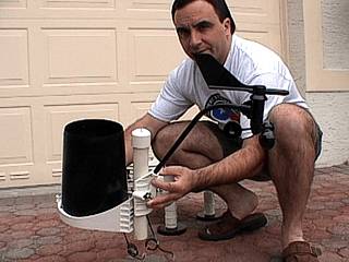
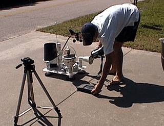
Jeff Gammons with former "Weathervine" (KG4PGA) uses his camcorder to document the parts and features of the Weatherlab III station for a Tech TV special. In this picture, the station is set up, with extra attachments, such as a large pastic dome housing a wireless gimballed camera, for display. |
HTML File "wxlab3.htm" - Developed By Chris Collura
To Return To The HOME Page Of This Site Click The "INDEX.HTM" Link Here!