
| This area shows the construction and completion of a new and highly improved version of the original "Weatherlab I" portable weather station prototype. This second unit, dubbed "Weatherlab II", is about half the size as its larger original version but far more refined in terms of weight, portability, and setup time. Designed to fit together with half as many bolts and wingnuts, the new station rests atop 5 large magnetic mounts and boasts the same equipment as the original "Weatherlab I". Packed volume is a little more than half as much (with a 25% weight savings) and setup time is chopped down to only a half hour. The "Weatherlab II" station uses an Oregon Scientific WM-318 weather station modified for "quick-release" setup. This station has two video camera systems, one fixed and the other remote-controlled moveable. The video pod on the station is a new remote-control unit with full up-down, left-right panning in a custom clear dome enclosure.
The entire station frame is painted high-visibility "taxi-cab" yellow and is complete with hailer-speaker, headlamps, and 4-strobe emergency / hazard beacon. The system also has mounting strap capability as well as the magnetic affixments. The platform is constructed of high-pressure PVC tubing (1/4 inch wall). The storm chasing possibilities of this device are very practical, even on long expeditions. Check out the pictures and construction of the "Weatherlab II" unit on this page! Note - This page may take a while to load on some SLOWER connections! |
|
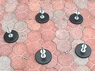
These are the five magnet mounts that are used to attach the Weatherlab II station to the top of the chase vehicle. Each magnet is 5" diameter and can hold up to 50 pounds. Each magnet was from a 3-magnet antenna mount bought cheap at Mike's Electonics HAM shop in Fort Lauderdale. The mount was removed and large bolt threaded through each hole and sealed with silicone. Another adjustable nut with large washer is where the weather station sits. Wing nuts attach the station securely to these mounts. These magnets work best for smooth metallic surfaces, such as the tops of most cars. |
|
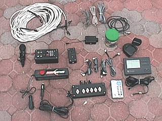
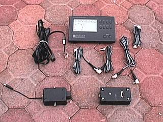
In this picture, the suite of "accessories" is shown for the new weather station. In the top of the picture are the connecting cables for most of the system. Also shown are numerous custom-built modules to work with various functions such as cameras and power supplies. It may look like a lot here, but most of what you see here is designed to be un-cluttered in a vehicle, such as under a seat. The main power controls are in the lower-left portion of this picture, including a Coleman 12V power pack. To the right, is the Oregon Scientific Weather station's console / computer. |
|
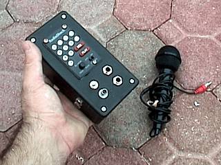
This is the custom-built audio / microphone controller for the Weatherlab II's speaker / hailer. It is built around the circuitry from Radio Shack's musical Powerhorn. Note that just the keypad from this popular PA unit is on the front of the custom audio control. The two connectors on the bottom are michrophone-level inputs, one RCA and the other 1/4" phono, switchable by the toggle switch just above it. The audio output is the 1/4" phono jack above and to its right. Two 12 V power adapter plugs are on the lower left side of the unit, near the palm of my hand. This allows 12VDC input, but another connector for 12VDC output to another device, like a daisy chain, for multiple 12V units. The musical portion boasts nearly 100 tunes, 5 programmable, plus hailer function by pressing a button on the upper-right side of the box, where an attached microphone like the one in this picture can be used. |
|
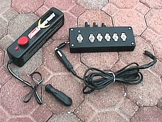
These are the main power supply / controls for the Weatherlab II. To the left is a Coleman 12VDC power pack. This replaces the internal batteries in the original weather station's power controller, is more powerful, and weighs less. This allows 12V power from your car's battery to pass to the weather station's electronics, but also has internal batteries so it can run for a short period without 12V from the vehicle. The Coleman unit has enough power to boost a weak car battery! To the top and right is the new and smaller power controller for the Weatherlab II. It has a master switch with indicator light, plus five toggle switches, the first for high-current, the second two for 12V power connections, and the remaining two for 12V power adapter (type "N") connections. This unit is much simpler and smaller because it has no internal batteries, and the camera controller(s) / audio module(s) have been removed (they are in their own separate external modules). |
|
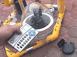
This picture shows probably one of the most intriguing features of the Weatherlab II station. This is a remote-controlled wireless video camera system. It is video-only, no audio. The camera is encased in a custom built dome structure and only has a 12V power connector to supply it power. The video is transmitted to a small receiver unit, up to 200 feet away, seen in the lower-right side of the picture. The remote control, held in my hand, allows the camera to pan up and down (90 degrees), left and right (240 degrees), via an X10 Ninja pan and tilt camera mount. The enclosure was built from PVC drain components where the dome is a clear egg dome from packaging for toy Matchbox cars! It was the only dome I could find with the thickness and dimensions for this system, and I gave the Matchbox cars to my neighbor's kid! |
|
This picture shows some of the main components for the weather station. On the top is the Oregon Scientific Weather station computer / console, connected to the weather station sensors via the cable to its left. In the lower-left is the controller for the fixed and wired video / audio camera (not the pan and tilt remote controlled one). This allows 12V power as well as audio and video to be received via a telephone type jack that connects the fixed video camera. It also has 12V in and out in both male and female type "N" power adapters. The unit to the lower-right is a voltage regulator where 12V goes in and out comes 3V, 6V, 9V, or 12V selectable by a switch. This will be set to 9V for operating the wireless video receiver unit, which requires 9VDC. Most power connectors used in this system have type "N" plugs, but are interchangeable for other sizes. |
|
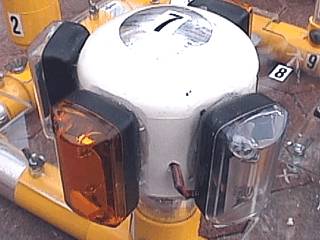
This picture shows the new solid-state strobe / emergency flashing light. It has no moving parts. Basically it is 4 12VDC flashing strobes (two yellow and two white) mounted on a PCV end cap and adapter to fit into the back of the weather station frame. The setup has 2 white flashers and one yellow flasher in the rear of the unit with one yellow flasher in the front. These small strobes can be obtained from any auto parts store that supplies custom / car neon lighting. |
|
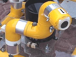
This is a picture of the enclosure and mount for the fixed wired video / audio camera system (audio included via internal microphone). This unit is designed to fit in the same place the RC wireless video-only system is on the Weatherlab II frame, or in the smaller connectors in its rear via an adapter, which is the white piece at the base of this unit. The adjustable portion is 2 PVC elbows that can turn on 2 axes up to 60 degrees. Contained in the top end is the X10 "spy" camera with built in microphone. The top end cap is removeable (twists off) and is secured via small wing nuts and has a 1/4" plexiglass window for the camera. A telephone type (RJ) connection in the lower far-left allows easy wiring hookup. |
|
This picture shows the rain guage unit for the weather station. It has not been modified itself, but has a telephone type connector for easy wiring hookups. The telephone (RJ) connector is the little white "box" to the lower-left side of the rain guage housing. |
|
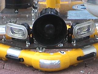
The lights and hailer speaker also did not undergo any major changes since the previous version of the Weatherlab station. The mounting screws were tightened, rough edges smoothed to fit it on this new frame, and silicone was applied to the speaker's swivel base to keep it from moving up and down. In this picture, the "powerhorn" type speaker and headlights can be seen on each side. |
|
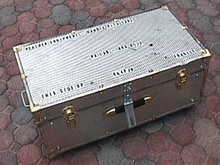
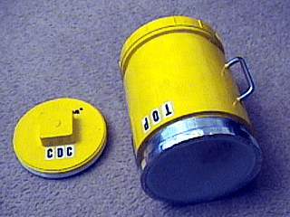
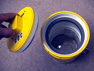
One of the most challenging tasks was to design (or modify) a case to tote the weather station equipment around the world. The box originally was a shoe chest made of wood covered with metal. This chest was reinforced with L-Brackets and metal straps, heavy duty handles and latches, heavy-duty wheels, and had its inside covered with dark felt. Even the cornered edges were drilled and bolted. Still, the chest only weights about 15 pounds. This is the same chest, which can pass through airport luggage, used for both versions of the weather station. The newer, smaller station also will use this chest, with more room available for other items, such as clothes. |
|
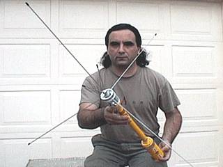
This is a picture of myself holding a highly modified version of Radio Shack's discone type (ground plane) scanner / HAM antenna. The PL-239 connector of the antenna unit was screwed into a PVC base bade from concentric end-caps (one 3/4" and the other 1-1/2". The 3 ground radials pass through holes of another PVC cap piece providing a fit that won't loosen the radials (lost radials have been a problem in the past). The cap piece is held to the yellow mast by 2 wing nut screws. The base of the antenna contains a feed-point BNC connector and fits to the 3/4" mounts on the Weatherlab II frame. The base of the antenna also opens, and the unit can be broken down to fit in an area about 20 inches long by 2 inches wide and tall. |
|
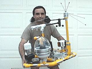
This is another picture of myself holding the entire Weatherlab II weather platform with everything installed except for the cabling. The entire unit weighs about 25 pounds in this configuration. The PVC tubing is 1-1/4" schedule 40 high pressure pipe. There are 3 connectors for 1-1/4" and 3 connectors for 3/4" attachments (some having stronger reinforced connections). Some mounting bolts were installed on the frame for farther ease of setup. The unit is painted yellow and marked with reflective aluminum tape for safety. The number labels allow easy identification of parts during assembly. |
|
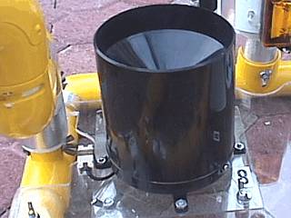
This is a picture of an addition to the "Weatherlab" weather station. This is an enclosure to make a compact camcorder (or digital / still camera) water resistant. It is built out of 6" PVC tubing couplers and features a 6" diameter plexiglass front window 1/4" thick. It is originally designed to handle a Sony Camcorder and obtain footage in wet environments such as heavy rain and / or blowing spray. It can even be used as an underwater camera enclosure with a 6" O-ring type seal in its rear. |
|
This is another picture of the back of the water resistant camcorder enclosure. The rear is a screw-type "cleanout adapter" for 6" PVC tubing. The unit is painted yellow for visibility, and floats. Note the two handles on each side of the unit, great for "storm-surge photography", naming this contraption the "Surge-Cam"! The plexiglass bracket inside is a standard camera mount via a tripod bolt. |
HTML File "wxlab2.htm" - Developed By Chris Collura
To Return To The HOME Page Of This Site Click The "INDEX.HTM" Link Here!