
| This area shows the construction and testing of a medium to large "high-power" Tesla coil. In this section, the 6-inch secondary coil setup is driven with twice the power as before, and with twice the tank capacitance! The tesla coil project is aimed mainly at the scientific and Tesla coiler community. I intend to use my Tesla coil for lightning demonstrations and entertainment. Note - This page may take a while to load on some SLOWER connections! |
This final variant of my Tesla coil is a moderate to high power unit. Basically, the medium power large Tesla coil seen on this site was modified to run at high power, near 3 KVA. First, and most importantly, a new power supply needed to be designed to meet the power requirements. Two new franceformer 12 KV / 60 mA NST's were obtained and paralleled with the other two 12 KV, 60 mA units. This yielded up to 12 KV at 240 mA with 120 VAC 60 Hz input. The enclosure for the four NST's is the same power supply cabinet used earlier, but with the control panel removed and the 120 VAC input and key switch relocated to the front-right side of the unit. The PSU is heavy, weighing nearly 100 LBS, and appears as a white box about a foot and a half wide and two feet long. It is on wheels and has a handle for easy moving. The HV outputs are on two PVC bushings at the rear and top of the PSU. To control the PSU, a KRM variac is used with a rating of 0-140 VAC at 20 Amps. The variac has a small voltmeter and switch built right into it for convenience, and can easly handle 2,400 KVA continuously (more intermittantly). On the actual Tesla coil itself, the doorknob capacitors were replaced with two Maxwell pulse discharge units, 0.03 uF each, in parallel for a total of 0.06 uF with a rating of 35 KV. The static spark gap fan was also ran through a smaller variac, mounted on the unit, to feed 0-140 VAC to the fan. Typical use would be to run the fan at or over 130 VAC intermittantly to speed up air flow through the gap. To reduce coupling and handle the higher power, the 1/4" inch copper tubing saucer-type primary was replaced with a flat spiral-type winding of 3/8" copper tubing. This new primary coil also has its innermost turn an additional inch away from the secondary base. The secondary coil was also coated with several more layers of varnish and polystyrene resin to be safe at the higher potentials expected. A oversized toroid, over 30 inches in diameter was also constructed for this new coil. To handle the extra weight, an additional 1x4 lumber board was placed under the center of the coil base just below the secondary. If all goes well, this new set up should produce sparks up to 5 feet in length. Starting with that, different spark gap configurations will also be tinkered with.
Lessons learned - Overcoupling of secondary causes running arcs! When the coiling gets more "big time" ... you will need to do it outdoors or else electronics in your home or garage will get zapped!
|
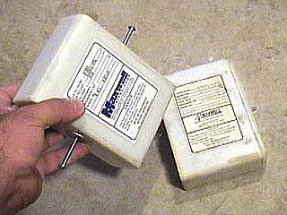
These are the Maxwell pulse-discharge capacitors to be used for this version of my high-power Tesla coil. They are rated at 35 KV and 0.03 uF each (30 nF or 3,000 pF). The 3 KVA version of this coil calls for a tank capacitance just under 0.06 uF, so two of these in parallel should be more than enough. Commercial pulse discharge caps are the absolute BEST for Tesla coil use, the only drawbacks being fixed large capacitance values and that they are usually very expensive. I got both of these off eBay for a little over $100, buying these new can cost near $1,000. |
|
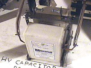
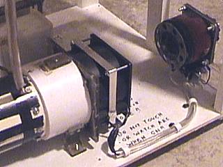
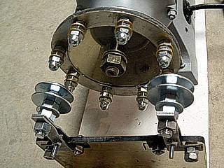
These are the two Maxwell pulse-discharge capacitors for this coil bolted into the base of the high-power unit. Two 0.03 uF capacitors in parallel make a total tank capacitance of 0.06 uF at a 35 KV rating. The two capacitors are held in parallel and sit on a plexiglass "seat" that holds them in place. Flattened 1/4 inch copper tubing forms the heavy duty / high current wiring for the caps. Note the safety spark gap just above the capacitors made with metal strapping and two carriage bolts. |
|
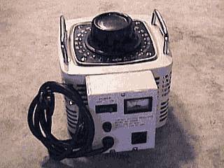
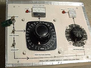
This picture shows a KRM variac to be used as the main power control for ths 3 KVA Tesla coil system. It is 120 VAC at 60 Hz input and puts out 0 to 140 VAC at up to 20 Amps. This unit is a "heavy duty" variac for 120 VAC and was had on eBay for under $100. It has its own on / off switch, fuse, even a voltmeter built right in! |
|
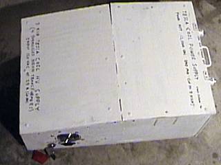
This is a picture of the new power supply for my high-power Tesla coil, or so called "white box". Inside, there are four (4) neon sign transformers in parallel, each rated at 12,000 VAC at 60 mA output. In parallel, the output is 240 mA at 12,000 VAC (with 120 V input). The output "bushings" emerge on the right side of the unit in this picture (with the handle in between). To the left, the 120 VAC input plug can be seen and safety key-switch next to the vent hole grille. Driven by the 0-140 VAC variac, this box can put out up to 14,000 VAC at 240 mA intermittantly (that's 3,360 VA) or 12,000 VAC at the same current continuously (2,880 VA). This unit produces thick flaming arcs on the Jacob's ladder test. |
|
In this picture, we can see the static Richard-Quick spark gap. This gap has also been modified to handle the higher voltages and currents near the 3 KVA values. First of all, a second 65 CFM fan was bolted to the end of the first quench fan of the same rating (fans are 120 VAC at 60 Hz and each consume 23 Watts). This axial flow "staging" shoudl increase, if not double the airflow through the static gap. The power input plug was also moved to the other side of the coil frame and equipped with a small 120 VAC 60 Hz input, 750 VA 0-160 VAC output variac to control the speed of the quench fans. This allows the quench fans to be "oversped" this increasing airflow through the spark gap even more, allowing extended run times at low-medium power with intermittant use near 3 KVA. Any more power, and a rotary spark gap will be needed. |
|
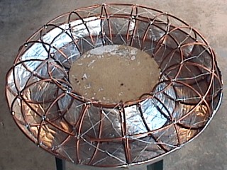
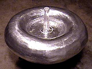
This is a picture of the construction of my "mega-toroid" to be used on the top of the new high-power Tesla coil. This toroid is entirely constructed from scratch. In the first stage, 16 circles of 1/4 inch copper tubing, 8 inches in diameter, are attached to a central wooden "hub" 12 inches in diameter. For forming, 6 perimeter circles of 1/4 inch copper tubing are bolted around at spaced intervals to complete the basic frame. The frame is then cross wound with steel wire and covered with a layer of aluminum tape, seen at the bottom of the toroid in this picture. The unit still needs a layer of spacking and final cover of smooth aluminum. The finished unit should have a major diameter of 22 inches and a minor diameter of 9 (more due to the coatings and layers to be added). |
|
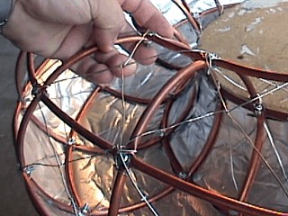
Here is a closer view of the copper tubing "framework" of the new large "mega" top load. Note the intricate criss-crossed steel wiring in each frame space formed by the copper tubing. The wires will support a primary layer of aluminum tape (the bottom of the toroid has this already applied in this picture), then a layer of non-cracking spackling paste which can be sanded smooth, a layer of varnish, then a final layer of aluminum as amooth as possible. |
|
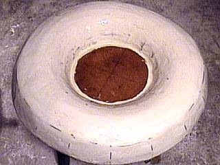
This is a picture of the large toroid covered with layers of spackling paste. The paste offers a lightweight coating that can be sanded smooth and painted with varnish before applying the outer and final layer of aluminum tape. |
|
In this picture, the large toroid is completed. It is covered with layers of aluminum tape and smoothed as best as possible. The aluminum covered connector in the center was made with a PVC pipe screwed into a metal flange for support. It should "mate" to the existing connection on the top of the high power coil secondary. On the other side in the center of the unit, two plastic cabinet handles (not visible) were added for easy carrying. The finished unit weighs in at about 25 pounds, and had a finished major diameter of 22 inches and a minor diameter of 9 (total diameter is about 31.5")! |
|
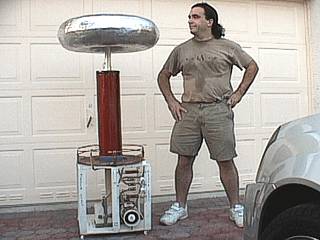
Here is a picture of myself and the completed high-power Tesla coil resonator unit. The unit is nearly as tall as me. I am sweating here in this picture after working to get this project done and first light. |
|
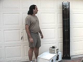
You are probably wondering how to test such a large power supply ... Well, I decided to construct a large Jacob's ladder, and a large one it is standing between six and seven feet tall! In this picture, I am standing in front of the Jacob's ladder, in a black wooden enclosure with plexiglass plates in its front. The variac and power supply to test are on the floor. |
|
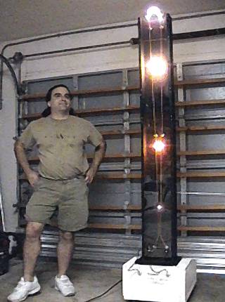
Here is a multiple-exposure picture, done by digitally adding four captured video frames, of the Jacob's ladder energized to 12KV as 3+ KVA (240 mA). The arc climbs from its point of initiation, only 1/2" apart to the top where the 1/4" copper tubing conductors are over 6" apart. |
|
As the power arc reaches the very top of the Jacob's ladder rig, it spreads into a beautiful flaming-hot streamer of plasma. The 60-Hz sound this thing makes is awesome. |
Primary Transformer
Output Voltage  : 12,000 VAC
Maximum Current : 240 mA
Frequency       : 60 HZ
Computed Power  : 2,880 VA
Computed Tank C : 53.1 nF (0.053 uF)
Primary Information (Overall)
Inside Diameter : ??"
Total Diameter  : ??"
Length Of Wire  : ??'
Average Radius  : ??"
Wire Diameter   : 0.375"
Wire Spacing    : 0.25"
Winding Type    : Flat "pancake" Archimedes spiral
Maximum Taps    : 9
Secondary Information (Overall)
Diameter                    : 6.5"
Length                      : 24.0"
Radius                      : 3.25"
Circumference               : 20.42"
Length Of Wire              : 1484.6'
Wire Guage                  : 22
Turns Per Inch              : 37.48
Aspect Ratio                : 1:3.69
Computed Inductance         : 29.86 mH
Computed Medhurst K         : 0.67
Computed Self-Capacitance   : 11.04 pF
Computed Resonant Frequency : 277.18 KHz
Computed Requirements
Actual Tank Capacitance       : 0.06 uF
Top Load Major Diameter       : 22"
Top Load Minor Diameter       : 9"
Computed Top Load capacitance : 34.49 pF
Required Primary Tap          : 7.0 Turns
Computed Resonant Frequency   : 136.50 KHz
|
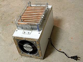
Here is a picture of a new spark gap being tested. This is a modified design from the TCBOR / Richard-Quick type gaps. In this gap, the electrodes are ten 5-Inch sections of heavy copper tubing with machined nuts fit snug in each end making it easy to bolt into the plastic frame via 1/4" nuts. The gap is fully adjustable allowing up to nine series gaps (some electrodes (copper tubes) can be removed if desired). The frame and electrodes sita atop a box where two fans (at least 60 CFM each) remove air from each end drawing air through the electrodes through a hole in the top of the box. The electrical connections are made via a 1/8" screw threaded through the two end electrodes on each side. This gap performed well up to 2.5 KVA (intermittently). |
|
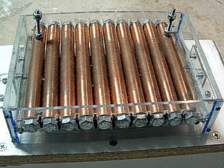
Here is a close-up of the top electrodes and plastic frame holding them in place. There are a total of ten electrodes giving a 9-gap series (each is spaced about 1/16" apart). Air is drawn into the gaps from above and into the box below via 2 fans. Note the two high-voltage connectors on each side. |
|
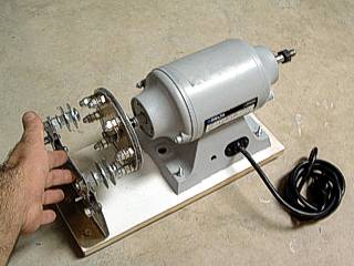
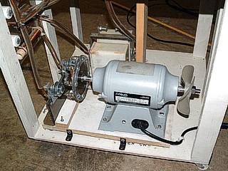
With over 3 KVA now available to this system limited only by a static gap, I decided to try my hands on building a rotary spark gap (RSG). In this case, I used a 3,600 RPM grider for the motor I found cheap and stripped it down. I cut a 5" high density plexiglass disk and fitted eight electrodes to it through two metal rings on each side of the disk. The spinning electrodes are 1/4" bolts with washers used to dissapate heat. The two stationary electrodes are made from 3/8" bolts (washers form the cooling "fins") and held in place via plexiglass and heavy-duty metal supports. The motor and assembly all sit on a wooden block. Designed as an ASYNCHRONOUS rotary gap, or ARSG, break rates can varied (using a variac) up to 480 BPS. |
|
Here is a close-up of the electrodes for the rotary spark gap. The two large static electrodes sit atop special brackets mating them to the insulating plexiglass which is attached to the wood base. The two long 1/8" bolts are for the high-voltage electrical connections to the unit. With alignment of two of the rotating electrodes on each side of the disk to the stationary ones, the gap fires across a gap of about 1/8" (total). The setup is designed to spin the disk at any speed up to 3,600 RPM allowing any break-rate up to 480 BPS. |
|
This is a picture of the rotary spark gap installed in the base of the Tesla coil with all electrical connections and mountings completed. The little fan was added on the right side of the motor in this picture to not only cool the setup, but allow wind-drag on the fan to slow the entire rotor for the spark gap down quickly (like a brake) when going to a lower BPS. |
|
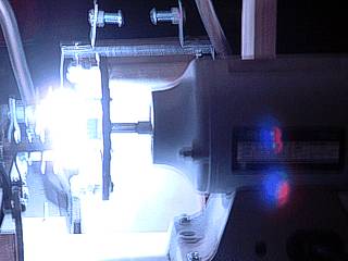
Here is the asynchronous rotary spark gap in action. Break rate is variable, and around 120 BPS in this picture. This gap is LOUD but performs much better than the static gap did. Not the safety gap for the two Maxwell capacitors in the upper portion of the picture. |
|
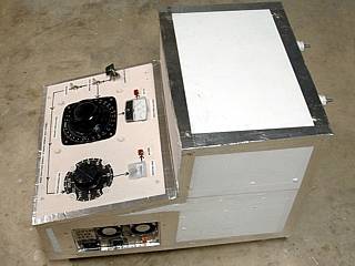
The high voltage power supply was also sleekened and redesigned. In this picture, all 4 NST's (each rated 12 KV at 60 mA) are contained in the wooden enclosure as well as main variac, switches, cooling fans, and auxiliary (motor control) variac. The unit is heavy but now you only have to worry about one unit, instead of all components separate as before. The schematic for this new supply box is very similar to the former set up with the exception of the extra variac for the motor speed control. The console is to the left side of the box and NST outputs (there are four) on the right. The power input and cooling fan assembly is in the left-front side in this picture and also has the outlet for the motor speed control. Castors make the unit easily moveable on a flat, hard surface. |
|
Here is a view of the new power supply console. Many components were retained, such as the key-switch and main power switches. The main switch energizes the main variac (0-140 V), which controls the voltage output of the NST bank (from 0 to about 14,000 volts). The second switch energizes the auxiliary variac (0-120 V) to control the spark gap motor speed. Each control also has its own indicator light and voltage meter. Vent air to cool the unit is drawn from a vent hole left of the console and exhausted to the right via two fans on the input power and cooling fan assembly. This unit is otherwise sealed. |
|
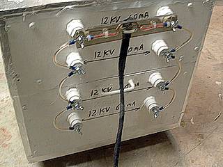
This is the view of the rear high-voltage output panel. There are four high-voltage outpus, one for each NST, that can supply 0-14,000 V at 60 mA. In this picture, all four are paralleled to yield 240 mA at that same voltage range. The high voltage cables are connected via a quick-connect guide I designed to the top of the connectors. The HV cables lead to the Tesla coil inputs itself and are two well-insulated high voltage wires in a sheath of electrical tape. |
|
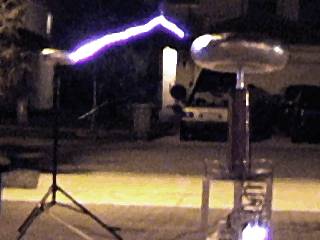
This is a video frame-grab of the first light of this big coil showing a fat and hot power arc jumping at least 4 feet from the oversized top load to a small grounded toroid mounted atop a tripod to the left. The grounded "target" was exactly 4 feet from the edge of the large topload. The big toroid REQUIRED a breakout point due to its size and smooth surface. Near full power, in this picture, the arc clearly completes the gap! Also note that this coil is too big to operate in the garage, and is being tested on the driveway - It drew a small crowd... Remember to "respect thy neighbors" if running one of these in front of your house ;-) |
|
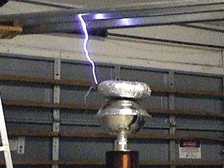
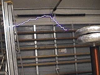
This video-grap shot shows the large coil set up with a grounded panel of sheet metal from a hurricane panel over the top load of the system (many different top loads can be used on this coil). The coil here is running at low power and throwing a power arc a little over 18" long to the grounded metal. |
|
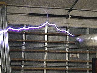
This is a video-grab picture of the Tesla system operating near high power. A single large power arc, one of many, slams the grounded metal (ladder and metal panel) to the left. This arc here was measured 52" in length (that's the distance, not the distance along the curved path of the arc)! |
|
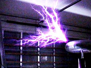
This is a video-grab picture of another large grounding power arc as the Tesla system operating was operating near high power. This arc hear was off the breakout point and past the metal panel and to the far side of the ladder, out of frame to the left. The length, measured, exceeded 60" (5-feet)! Note the little branching streamer midway across the arc channel reaching upwards. |
|
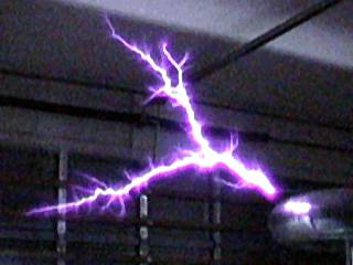
In this picture, we see a multiple (combined-video frames) exposure to capture what a 3KVA coil looks like in your garage at full power. Many arcs reach out and hit the ceiling, over 4 feet above the breakout point, others branch left at nearly 5 feet in length. This thing was actually shaking the floor at full power! |
|
This video-grab picture, taken at another exposure level, shows what the arcing looks like to the unaided eye. The discharges here are up to 5 feet in length. Time to run the coil outdoors. |
|
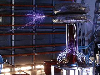
This is a digital picture (2-second exposure) of the coil running near full power. Arcs here are up to 5 feet in length. This was after re-designing and trouble-shooting the static spark gap. Note the "banjo-effect" caused by the long exposure as well as some power arcs going up and striking the rail for the garage door opener (not good because the unit had problems afterwards). |
|
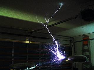
Running near full 3KVA power, the Tesla coil sends a long (at least 5 feet) power arc right through the ceiling! |
|
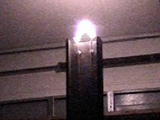
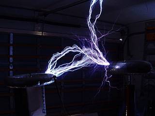
Here we can see an undesired effect on the secondary called "racing arcs". These sparks are originating from the top terminal of the secondary and running down the surface and striking the grounded strike rail. This is most likely due to overcoupling and often solved by raising the secondary an inch up with a plastic or wood plate. The secondary was to also be "super insulated" after this by impregnating it within layers of fiberglass resin. |
HTML File "tcpart8.htm" - Developed By Chris Collura
To Return To The HOME Page Of This Site Click The "INDEX.HTM" Link Here!