
| This area shows the construction and testing of a small "table-top" Tesla coil. In this section, scrap materials were used and a 2.5 inch secondary coil was designed for high efficiency and ease of use. The tesla coil project is aimed mainly at the scientific and Tesla coiler community. I intend to use my Tesla coil for lightning demonstrations and entertainment. Note - This page may take a while to load on some SLOWER connections! |
This Tesla coil was constructed using leftover materials as well as dismantling of the twin Tesla coil shown earlier in this site. This is a coil designed to be set up easily and operated from a table top requiring only a dedicated RF ground as well as a standard 120 VAC outlet. The unit is designed for efficiency and operates with only 1/4 KVA of power. The coil is a basic 1/4 wave design with a secondary that is wound 13.5 inches long by 2.5 inches wide on sealed PVC pipe with AWG #22 magnet wire. The power supply is a 10,000 volt, 23 mA OBIT (Oil Burner Ignition Transformer) unpotted and sealed in a smaller wax enclosure. The tank capacitor is three 2500 pF, 30 KV doorknob capacitors in parallel for a total of 7500 pF (0.0075) uF. The primary is about 10 turns of 1/4 inch copper tubing wound in a 30 degree inverted cone with a tap at about 5.4 turns using an existing 8x4 toroid. The spark gap is a modified RQ / TCBOR type static gap with 4 stainless steel tubes (3/4 inch by 3 inch) in a plexiglass box blown by a 12 VDC muffin fan with its own power supply. The controls are only a main power switch and a 300 watt variac control for the HV transformer. The base of the secondary is set to be hooked up to an RF ground and has a wing not for easy connection. The tap of the primary is mad to the desired tap point and a HV supply "bus" ring of copper tubing that goes around the entire primary. No strike rail was used on this model of the Tesla coil. The HV transformer is also protected with two chokes made of about 100 turns of AWG #22 magnet wire wound around 2 cores of 1" PVC pipe and sealed.
Lessons learned - You can have a small Telsa coil and it produce suprisingly nice sparks with little power consumption. Slightly better performance (up to 10-12" spark output) was achieved by replacing the dimmer switch with a small 0-140 VAC variac! Eventually, the small OBIT inside this unit failed during an extended run (it was over 25 years old). The unit was modified so that a variac outlet was installed in the back of the unit and HV bushing for input. Now the unit can be run with an external high voltage transfomer, such as an OBIT or 12 KV / 30 mA NST.
|
The diagram above is the schematic for my table-top Tesla coil. The AC input runs through a 0-140 VAC variac (rated at 300 watts) to a 10,000 volt 23 mA oil burner ignition transformer. The primary circuit of the tesla coil assembly is series connected with the 0.0075 uF tank capacitor. The spark gap is a modified TCBOR / RQ static gap with 4 electrodes and is parallel connected in the circuit. The output of the HV transformer also flows through 2 chokes (one for each HV output) before being fed to the tank circuit. The capacitor is 3 doorknob capacitors (each rated 30 KV at 2500 pf) for a total of 7.5 nF (0.0075 uF). The secondary is connected to RF ground at one end (not the mains ground, ofcourse) and the other end is the output HV terminal for the coil. The spark gap quench fan is powered by a small 12 VDC cooling fan running off a small 12 VAC step-down transformer and a rectifier to power the fan. The fan power supply runs off a main power switch for the coil before the variac circuit. A rather simple design but works great. |
|
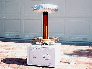
This picture shows the completed table-top version of my Tesla coil. Believe it or not, this coil was constructed using all SCRAP materials, scavenged from my old demo (severely out-of-tune) twin coil and left-over parts. The unit is completely self-contained and stands about 2 1/2 feet tall. It is super-easy to set up and operate and is relatively efficient for its size and low power. The entire unit weighs less than 30 pounds. |
|
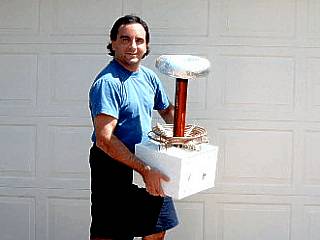
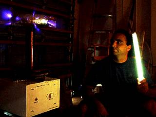
This is a picture of myself holding the table-top version of my Tesla coil. The unit here is small, light weight, and completely self contained and weighs less than 30 pounds. All you have to do is ground it to a dedicated RF ground and plug it in! |
|
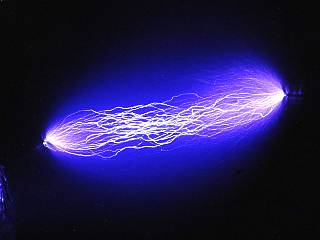
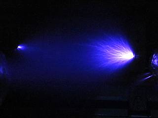
This is a picture of a power arc over 6 inches in length between the top 8x4 toroid of the table-top Tesla coil running at full power and a grounded toroid nearby. Note the "cloud" of ionization surrounding the brighter power arcs. Not bad for a 23 mA, 10,000 volt oil burner transformer. |
|
This picture shows the corona effect and streamers between the 8x4 toroid of my table-top Tesla coil at full power and a breakout point on a grounded toroid 10 inches to the left. Note the corona to the lower, left of the breakout point on the left side of the picture. This puts total streamer length at 10 to 12 inches, nearly a foot. |
|
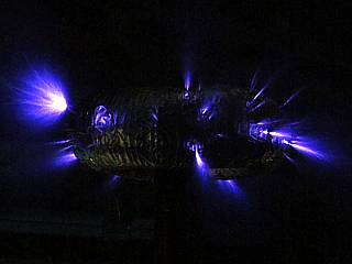
In this picture, multiple breakouts randomly occur on surface imperfections on my 8x4 toroid of my table-top Tesla coil running near full power. Note the brush-like nature of the corona and small streamers. RF energy was also high during this point, able to completely jam an AM radio 50 feet away! |
|
This is a picture of myself powering up my table-top Tesla coil while holding an fluorescent light a few feet away. The lamp glows brightly in the intense RF field around the coil. Note the corona around the toroid. |
Primary Transformer
Output Voltage  : 10,000 VAC
Maximum Current : 23 mA
Frequency       : 60 HZ
Computed Power  : 230 VA
Primary Information (Overall)
Inside Diameter : 3.4"
Total Diameter  : 8.25"
Length Of Wire  : 8.13"
Average Radius  : 2.90"
Wire Diameter   : 0.25"
Wire Spacing    : 0.25"
Winding Type    : 30 Degree Inverted cone
Maximum Taps    : 10
Secondary Information (Overall)
Diameter                    : 2.25"
Length                      : 13.50"
Radius                      : 1.13"
Circumference               : 7.07"
Length Of Wire              : 289.07'
Wire Guage                  : 22
Turns Per Inch              : 37.48
Aspect Ratio                : 1:6
Computed Inductance         : 2.10 mH
Computed Medhurst K         : 0.90
Computed Self-Capacitance   : 5.14 pF
Computed Resonant Frequency : 1532.23 KHz
Computed Requirements
Actual Tank Capacitance       : 0.0075 uF
Top Load Major Diameter       : 8"
Top Load Minor Diameter       : 4"
Computed Top Load capacitance : 13.26 pF
Required Primary Tap          : 5.4 Turns
Computed Resonant Frequency   : 809.64 KHz
HTML File "tcpart7.htm" - Developed By Chris Collura
To Return To The HOME Page Of This Site Click The "INDEX.HTM" Link Here!