
| This area shows the construction and testing of a medium to large class Tesla coil. In this section, the previous coils were dismantled and a new larger coil, with a secondary over 6 inches, was redesigned and constructed for maximum efficiency at a power if about 1,440 watts. The tesla coil project is aimed mainly at the scientific and Tesla coiler community. I intend to use my Tesla coil for lightning demonstrations and entertainment. Note - This page may take a while to load on some SLOWER connections! |
The Tesla coils so far on this page were of low power and experimental in nature. This section shows a larger and more efficient coil built from scratch and within stricter adherance to the electrical rules involved in Tesla coiling. The new coil is a 1.5 KVA coil running off a bank of two 12KV, 60 mA NST's and sports a 6-inch secondary made from scratch! The secondary form for this coil is made of layered acrylic fabric sheets stiffened with styrofoam to form a 6-inch diameter cylinder and laminated with many layers of polystyrene resin (fiberglass clear boat resin). Each end is sealed and capped with 1/4 inch plexiglass and the form is close-wound with about 900 turns of #22 magnet wire. The tank circuit for this coil is a modified RQ spark gap with 10 3" x 3/4" copper pipe electrodes and 10 doorknob capacitors in parallel (each is 2500 pF at 30KV) yeilding 0.025 uF. The entire tank circuit is wired with 1/4" copper tubing encased in clear neoprene and heavy metal strip for the caps. The primary is a 15 degree inverted cone of 1/4" copper tubing with 1/4" spacing (about 10 turns tapped at 8). The support for the coil is a wooden frame about 18 inches high on casters for easy movement. There are three safety gaps, two formed by bolts on the doorknob EMMC bank, and one on the "supply panel" where two RF chokes (each 100 turns #22 wire on 1" PVC form) and HV terminals are. The panel safety gap forms a spark gap between the earth (RF) ground post and the two HV supply inputs. The toroids are easily interchangeable atop the secondary and are the two 11" salad bowl halves, or oversized (6" by 18" diameter) toroid. The system is supplied by a separate power supply which supplies the two HV terminals as well as spark-gap quench motor power. This unit contains two 12 KV 60 mA NST's in parallel with 130 uF PFC capacitor in parallel with each NST input. There is key switch and main power switch with indicator light which feeds a 10A variac for the NST's. A voltmeter is fed by a diode and 12V transformer showing 0-15 (x1000) volts. When powered up via the main switch, a buzzer sounds (which also can be silenced by a switch) as a HV warning alarm. There is also a dual outlet, one for the variac output and the other for the quench motor, also controlled by a switch. There are four HV outputs in the back of this unit on PVC cap "bushings". Two are from one NST, the other two are from the other. A "bus strip" parallels the two NST's at these output terminals. The HV wires are #14 house wire encased in neoprene tubing, and connect the PSU with the Tesla coil unit. The PSU also is on wheels for easy moving as it weighs about 75 pounds. This makes this Tesla coil system a 1440 Watt (1.5 kVA) medium power Tesla coil capeable of generating 4 foot plus arcs under the right conditions! Most pictures of this project are of the completed coil and setup / spark pictures. The only down side is that the older Tesla coils, including the dual unit and original PSU, were dismantled for the parts to build this version.
Lessons learned - Toroids and top-loads are VERY important for Tesla coil spark types! Further modifications to this version include using the 4x24 secondary (these are easily changed) from the dismantled old coil, using a well quenched spark gap. Also modified the copper tube type connections to reduce any "sharp" turns and solder them where necessary. Spark gap quenching is also very important, and an additional fan was added to improve quench air flow over the spark gap electrodes. Also modified secondary connections so that they can be changed quickly and easily. Also, you can use PVC for your secondary as long as it is thin-walled, sanded, dried, sealed FIRST, then wound and sealed thoroughly with urethane varnish. A similar secondary using boat styrene resin was easier to make, but cracks too easily when heated. Also made a supply "bus" of copper tubing with both ends connected to the HV primary supply post so that taps on the primary can be made ANYWHERE around the coil rather than just near the HV post.
|
The diagram above is the schematic for my fifth and big (6 inch) Tesla coil design step. In this configuration, the AC power enters a separate power supply box with high voltage and mains level (120 V) outlets. The power supply unit contains a key switch as well as illuminated main switch for the power input. Upon power up of the mains switch, the power supply for the cooling / vent fan is energized, which also powers an audible buzzer (warning) that can be silenced via a switch. The mains-level power also is sent to a switchable outlet which supplied the spark-gap blower motor (this also has an on-off switch). The remaining power goes through a powestat variac where it is varied from 0 to 120 V. The output of the variac is also routed to another outlet (if needed for convenience) and to two separate neon sign transformers rated at 12,000 V, 60 mA each. Each NST input is controlled by its own on-off switch and has a 130 uF (330 WVAC) power factor capacitor in parallel with its input. Yet another branch off the variac power output goes to a small transfomer, diode, and 15K resistor to power a small voltmeter. The range is from 0-15 volts, but is calibrated so that 15 x1000 = 15,000. The outputs of the NST's have their separate outputs emerging from the back of the unit via PVC HV bushings (made from 1/2" PVC end caps and bolts). These two outputs can easily be paralleled for an output of 12 KV at 120 mA. If one transformer is energized, 60 mA at the same voltage is produced, but the outputs have to be un-paralleled to prevent leakage into the other unpowered NST. The actual Tesla coil unit is separate from the power supply, as one would expect from a medium to high powered TC system. The high voltage inputs arrive on PVC bushings and are routed through two chokes (100 turns of #22 magnet wire on a 3/4" PVC core). A safety spark gap is between the two HV bushings and RF ground for NST protection. The output of these terminals goes right to the tank circuit consisting of 10 turns (tapped at 8) of 1/4 copper tubing, 10 2500 pF 30 KV doorknob capacitors in parallel (for a total of 0.025 uF), and a RQ static spark gap. The RQ gap has 10 copper pipe (3" by 3/4") electrodes in series with 9 gaps each spaced 1/32". The capacitor bank also has a small safety spark gap. The secondary is a custom built 6 inch by 24 inch and has roughly 900 turns of #22 magnet wire. The secondary is connected to RF ground at one end (not the mains ground, ofcourse) and the other end is the output HV terminal for the coil. Image is scaled ... Click on the image to the left for the full size picture. |
|
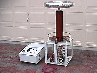
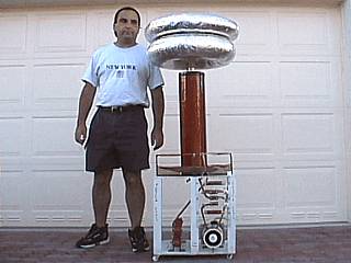
This picture shows the entire 6-inch Tesla coil system. The entire unit stands about 4 1/2 feet high. The power supply unit is to the left of the Tesla coil and the neoprene-encased high voltage hookup wire in the foreground. The unit was spray-painted white and appears as a work of art in addition to it being an electrical device. |
|
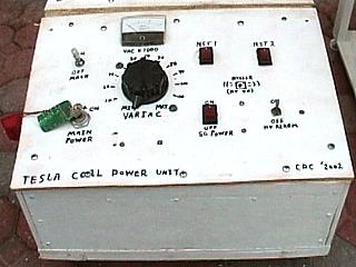
Here is the front control panel for the big Tesla coil power supply unit. Note the key switch to the lower left of the panel. Above that is an illuminated main power toggle switch. The large dial below the volt-meter is the 0-120 volt variac control. The volt-meter displays 0-15 (calibrated for 0-15,000 volts). The top two switches in the upper-right are the two internal NST power switches. The one below the first NST switch turns on an off the spark-gap 120 VAC power outlet. The buzzer for the high voltage warning is in the center of the 4 switches to the right and can be silenced by turning off the lower right toggle switch. The HV warning buzzer sounds whenever the main toggle switch above the key switch is energized. |
|
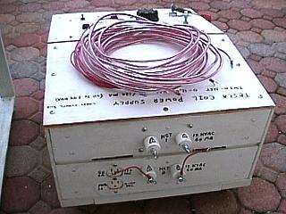
Here is the rear panel of the big Tesla coil power supply unit. The high voltage hookup wire was placed atop the unit. This wire is solid #12 wire with 600 V insulation. The hookup lines are 20 feet long and 2 are enclosed in aquarium airline (neoprene) tubing for the HV connections with one uncovered for the RF ground connection. This allows the power supply to be operated 20 feet from the coil. The back of the PSU has 4 high voltage bushings made from PVC pipe end caps and wing-nut bolts for easy connections. The top and bottom connectors each put out up to 12,000 volts at 60 mA. The connections in parallel yeild the same voltages up to 120 mA. The outlet in the far lower left is for the spark gap motor (120 VAC) as well as an additional 0-120 VAC variac output. |
|
This picture shows the high voltage, RF ground, and spark gap blower power connections on the Tesla coil base. The two wing-nuts and bolts in the PVC end caps are the two high voltage power inputs. These both pass through RF chokes of 100 turns of #22 wire on 3/4-inch PVC tubes to prevent damage to the power supply (neon sign transformers). The high voltage also goes through a safety spark gap (three 3/4 inch copper tubes in the center of the panel with the center tube the RF ground). The center electrode in the safety gap also has a wing-nut so the dedicated RF ground can be connected. The panel is supported by clear plexiglass. The 120 VAC plug at the bottom is for the connections to the blower motor in the RQ spark gap quench fan. |
|
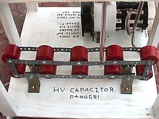
This is a view of the EMMC (Enhanced Multiple Mini-Capacitor) section on the base of the larger Tesla coil. The MMC is made from 10 doorknob type capacitors each rated at 30 KV, 2500 pF. The caps are in parallel via bolts and stiff metallic strips. The supports are 1/4 inch thick plastic "L" brackets. Note that the inside bolt head of the "L" brackets also form a mini spark gap to protect the capacitors (I have seen this gap fire in tests). The total capacitance yielded by this setup is 0.025 uF. Note that the tank circuit connections are done with 1/4 copper tubing encased in neoprene tubing. The unit in the upper right is the Richard Quick static spark gap. |
|
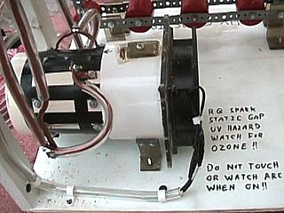
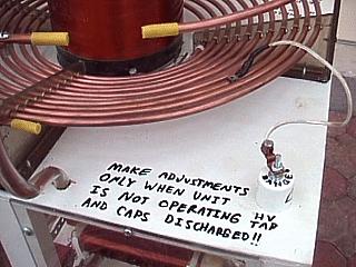
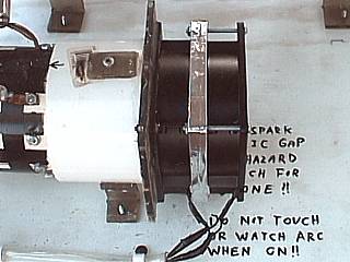
This is a side view of the the Richard Quick static spark gap for my 6 inch Tesla coil. The 120 VAC, 65 CFM fan is on the right side of the gap housing. The PVC collar and housing for the tubing electrodes mate to form the gap assembly. The tank circuit connections can be seen to the right. When these are removed, the entire gap assembly slides out (to the left in this picture) for easy cleaning of the electrodes while the fan assembly remains in place. The black electrical tape covers the adjustment grooves for the electrodes. Air flows from left to right in the unit in this picture. Note the warning messages to the right! |
|
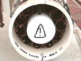
This is a view of the inlet to the Richard Quick static spark gap for my 6 inch Tesla coil. Air is "sucked" into this side and flows over the copper-pipe electrodes and exhausted out the fan at the other side. In this picture, we can see the 10 3" by 3/4" copper tubes spaced no more than 1/32" apart to formn 9 series gaps. The main form is a section of 4" ID PVC pipe. Note the small PVC pipe and end cap to increase the speed of incoming air and force it to flow more over the electrodes. The 1/4 inch strip of plexiglass barely visible in the top is the arc shield for the first two copper electrodes. |
|
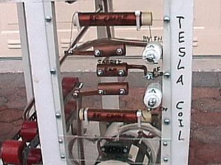
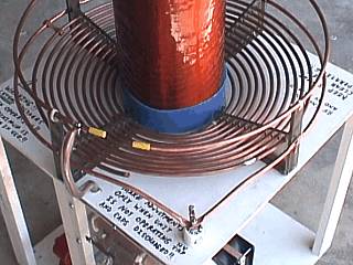
This view shows the primary coil and taps of the large Tesla coil. In this picture, one can clearly see the inverted cone type "saucer" primary coil at an angle of 15 degrees. The coil has about 11 turns of 1/4 copper tubing and is tapped at turn 8 in this picture. The tap "post" is the PVC end cap type high voltage bushing to the lower right. The small tap wire has a fuse holder soldered to its other end to taps can be made by clipping it on the primary quickly and easily. Note the stop-gap approach to warning lettering on the un-cluttered area. The strike rail and ground connections can also be see to the left and top of the picture. |
|
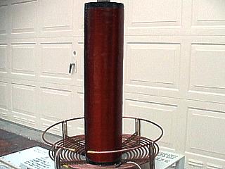
The secondary coil for the new 6-inch tesla coil was actually constructed from scratch. It started out as two acrylic sheets wrapped around styrofoam 6-inch disks to form the "skeleton" onto which layer upon layer of urethane sealant was applied until it was fairly stiff. The next step was several layers of styrene resin used in boat repair (two chemicals mixed and applied before their 15-minute cure time). Two plexiglass 6-inch circular end-caps were placed on each end of the unit and covered with more boat styrene. After many coats, the form was sanded and smoothed, sealed with more urethane, and finally wound on a home made wooden lathe with #22 AWG magnet wire. The winding is 6 inches in diameter and about 24 inches in height (with 1 inch unwound on each end of the 26-inch form) and has roughly 900 turns. The wound form was then convered with more coats of boat repair styrene and finished with urethane sealant. The plastic disks at each end had a bolt with a plastic end affixed to the disks before being sealed in styrene. These served as the supports for the lathe, as well as the connections on each end of the finished unit. A PVC pipe and end cap on the top of the secondary makes attaching the top loads easy. I wanted to avoid using PVC on this unit and acrylic tube was so hard to come by, so I took this arduous approach. |
|
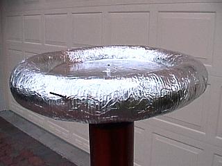
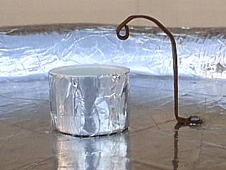
This picture shows one of many top loads that can be attached to this version of my Tesla coil. The top load here is a toroid made from 4" aluminum vent duct around a 20-inch wooden disk. Aluminum tape covers and holds the entire unit together. The final skin is aluminum foil held on with spotty contact cement (all sections of foil are electrically conductive). The bolt in the middle holds a PVC end cap in place to attach the toroid to the top of the secondary via a section of PVC. A wire connects the secondary to the underside of the top load via a screw terminal and clip. Note the nail in the front of the toroid, that is to help initiate spark breakout. |
|
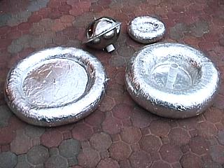
These are the various toroids, or top loads, that are designed to fit atop the 6 inch Tesla coil. Clockwise from the upper left, the 11-inch semi-sphere was made from two steel salad bowls and attaches via a PVC fitting and screw terminal. The small toroid is about 10 inches in diamaeter and 4 inches tube diameter. The big one is about 22 inches with a 6 inch tube diameter. Finally, the other big one to the lower left if about 22 inches by 4 inches. All are tried atop the new coil for various effects. |
|
Here is a picture of myself standing next to the improved big Tesla coil. The entire unit, with two oversized toroid top-loads, stands about 5 feet (60 inches) high. I am 5' 7" tall. |
|
This picture shows the second quench fan added for increased spark-gap performance. The second fan is the same 65 CFM 120 VAC rating as the other one and is bolted onto the existing fan for increased axial flow of air. I don't know what the new CFM (Cubic Feet Per Minute) is, but it appears the speed of the airflow over the spark-gap electrodes has about doubled. |
|
Here is a rather ingenious way of mounting different top loads (toroids) to the secondary terminal of my big Tesla coil. A metal clip made out of flattened scrap copper tubing that forms a contact from one metal surface to the other. In this picture, a PVC pipe with 1 3/4 coupler coated with aluminum foil forms the contacts for the metal clip. This works great at ultra-high voltages at RF frequencies. The toroids and top loads have such connectors as well as the top terminal of the secondary. |
|
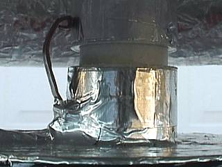
This picture shows the "mating" terminal of the big Tesla coil's secondary output forming a connection to the top-load (toroid). The conducting surface of the toroid and "corona ring" of the top of the new secondary electrically "connects" via a simple copper "clip" from a flattened section of copper tubing. Between the two aliminum coated PVC couplers, a short piece of 1 3/4 PVC pipe completes the connection, as long as the metal clip contacts the metal surface of the top-load. |
|
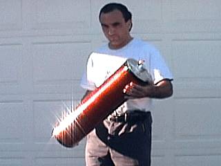
This is a picture of myself holding the new and improved secondary coil for the big Tesla coil. This one was made from thouroughly dried and sealed electrical grade PVC thin-walled pipe and is 6 1/2 inches in diameter. The winding length is 24 inches of #22 magnet wire and has been sealed with nearly 20 layers of urethane varnish (note the gloss). Each end is sealed with plexiglass and epoxy and the top-end has a special "mating" piece of 1 3/4 PVC coated with aluminum foil tape which also forms a "corona ring" on the end of the unit. The bottom end has a mounting bolt for attachment to the Tesla coil base. The total length of the tube is 26 inches (one-inch unwound at each end). Absolutely no wires or bolts are exposed inside the tube! |
|
This picture shows the changes made to the primary tap of the big Tesla coil. Here we can see a high voltage supply bus formed by a continous loop of copper tubing below the strike rail bolted to the outer edge of the plastic supports. Both ends of this supply bus terminate at the original high voltage tap. Using this method, not only can the primary be tapped at 8, 9, or 10 turns, but also at 8 and a 1/2, 9 and 3/4, etc! In the picture above, the coil is tapped at about 10.6 turns via a moveable small metal clip made from flattened copper tubing in the upper left corner of this picture. In addition to the improvements made since first "light" of this bigger coil, the coil has yet a larger secondary (6.5 inch sealed PVC), improved spark-gap quenching, and most "sharp" and redundant turns in the copper tubing of the primary and tank circuits eliminated for better RF performance. The blue shield over the first 2 inches of the secondary also is new. It is the bottom section of a vinyl fishing bait bucket and insulates the bottom end of the secondary from primary arcing, and also reduces "running" arcs over the secondary. A 1-inch thick by 6-inch diameter styrofoam disk placed under the secondary also decreased over-coupling and eliminated the running arc issue. |
Primary Transformer
Output Voltage  : 12,000 VAC
Maximum Current : 120 mA
PFC Capacitor   : 260 uF
Frequency       : 60 HZ
Computed Power  : 1440 VA
Primary Information (Overall)
Inside Diameter : 8.0"
Total Diameter  : 17.2"
Length Of Wire  : 32.02'
Average Radius  : 6.30"
Wire Diameter   : 0.25"
Wire Spacing    : 0.25"
Winding Type    : 15 Degree Inverted cone
Maximum Taps    : 11
Secondary Information (Overall)
Diameter                    : 6.5"
Length                      : 24.0"
Radius                      : 3.25"
Circumference               : 20.42"
Length Of Wire              : 1484.6'
Wire Guage                  : 22
Turns Per Inch              : 37.48
Aspect Ratio                : 1:3.69
Computed Inductance         : 29.86 mH
Computed Medhurst K         : 0.67
Computed Self-Capacitance   : 11.04 pF
Computed Resonant Frequency : 277.18 KHz
Actual Tank Capacitance       : 0.025 uF
Top Load Major Diameter       : 22"
Top Load Minor Diameter       : 4"
Computed Top Load capacitance : 26.17 pF
Required Primary Tap          : 10.6 Turns
Computed Resonant Frequency   : 148.17 KHz
|
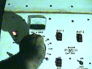
Here is a picture of the control panel of the power supply for my latest big Tesla coil being "ramped" up by turning the variac slowly clockwise. In this picture, the voltmeter indicates "5" for about 5,000 volts out on the neon sign transformer. The spark gap begins firing at around 4-5 KV out (about 1/4 power on the variac). |
|
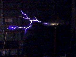
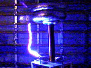
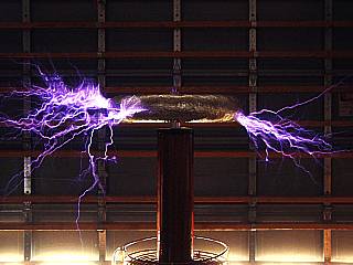
This is a picture of my latest and greatest Tesla coil being powered up to near full power for the first time. In this picture, a beautiful streamer makes its connection with a grounding rod about 3 feet from the coil. The way the coil behaved was pretty interesting. When ramped up to full power, a small "brush type" discharge appeared at the 4x24 toroid breakout point (nail). In the course of about 30 seconds, the "brush" evolved into branching, withering streamers up to 40 inches in length. Two things cause this "latency", which is very normal for this type of coil. One is that the quench fan on the spark gap has to get up to speed thus allowing the caps to charge more before the gap fires. Second, the Tesla coil, its topload (toroid), and the earth (RF ground) are all capacitors, and the high-frequency RF field also creates a tremendous amount of static electricity, which has to "build up". |
|
This is a picture of a lonely first streamer about 20 inches in length that came out of a break-out point on my large 4x22 inch toroid running on my coil at about 1/2 power. The breakout point is a 3 inch nail on the surface of the toroid. |
|
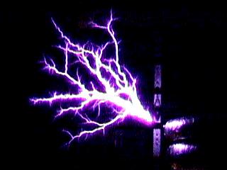
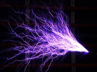
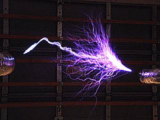
This longer exposure video frame grab shows the beautiful display of hot, multiple streamers coming off the break-out point when running my coil at near full power with two over-sized toroids (6x24 stacked atop a 4x24). These streamers are hot and very loud! Maximum spark-length here is about 36 inches. |
|
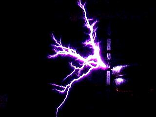
This is another exposure video frame grab showing the branching effect of the multiple streamers coming from the breakout point with two toroids on top my coil running near full-power. Note that there are two white-hot streamers, both going out of frame, one upwards and the other to a grounded cable near the floor. These streamers were approaching 40 inches in length. |
|
Here is a video grab showing my large Tesla coil running at full power with a 4x24 secondary (from my older coil I dismantled). It performed nearly as good as my 6x24 secondary! In this picture, a nasty, white-hot power arc takes a direct hit on the strike rail. Note I have two break-out points, one on each toroid. I removed the bottom one after this to reduce these strike-rail and even some primary power arcing (I counted at least 3 hits to the primary tap wire, and all fired my safety gap - but the coil just kept running)! The power arc in this picture is at least 24 inches long. |
|
This is a picture of the spark breakout from a nail on the 4x22 inch toroid of my Tesla coil running near full power. The streamers are over 30 inches in length. This picture is a 3-second exposure taken from a Fuji digital camera. |
|
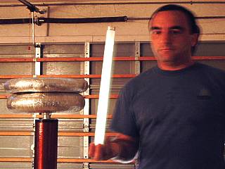
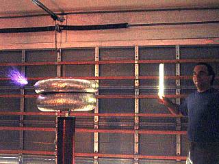
Here is another picture of myself holding one end of a fluorescent tube with my big Tesla coil running at 1/4 to 1/3 power in the background. This is a two-second time exposure taken with a Fuji digital camera. The coil is producing a small discharge (not visible to the left) and enough RF energy to light the tube between 5 and 10 feet from the coil. Another strange phenomina was that any ungrounded metal objects in the garage within 15 feet of the coil running even at low power produced a small arc to my fingers when touched. I was able to draw a small 1/4 to 1/2 inch arc from the metal handlebars of my bicycles to my finger tip giving me a tiny RF burn! Sort of scary effect of being in the "reactive RF near-field" of such a transmitter (Tesla coil). |
|
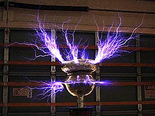
This picture shows my big Tesla coil running near full power with the smaller original top-load used on my earlier coils (a ball made with 2 steel 11-inch salad bowls topped with a 4x12 inch toroid). With nearly 1.5 KVA, the breakout length is slightly smaller with streamers less than 2 feet but much more frequent due to the smaller capacitance of the old top-load. |
|
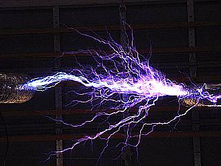
In this video frame-grab, I am holding a grounded discharge near the breakout points on my coil running near 3/4 full power. Again, white-hot power arcs, loud and terrifying, leap to the grounding rod. The power arc clearly is a brilliant blue and white channel of hot plasma. Note the "noise" in the video created from the intense RF field generated near the coil. My Canon 2000 EOS SLR camera simply kept "locking up" when I tried to take pictures this close, and only came back if I removed and replaced its batteries. Finally, my SLR took on a mind of its own and rewound the film (with a full unused roll in it) so I used the camcorder instead for these pictures! |
|
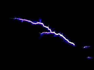
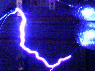
In this picture, with my big coil running at full-power, a power arc leaps from one breakout point (nail) on the coil toroid to a second nail on a grounded toroid at a distance of 36 inches (I measured it). |
|
This picture shows my big Tesla coil running at about 1/3 power and producing a discharge up to 10 inches from its breakout point. The RF energy generated lights the fluorescent tube in my hand as I stand at least 5 feet from the coil. |
|
This is a picture of a power arc slightly more than 3-feet in length (my personal record so far) from the toroid of my Tesla coil at full power to a grounded toroid spaced slightly more than 36 inches (measured with a tape measure). Exposure is 3-seconds with a Fuji digital camera and also captures countless streamers at nearly the same length. |
|
This picture is a 3-second exposure taken with a Fuji digital camera of my big Tesla coil running at full power. With the main breakout point (nail) removed, spark breakout was more random and energetic. The breakout seemed to favor the left and right sides of the 4x22 toroid in this picture. Note the one streamer extending below and to the left of the strike rail on the lower-left side of the picture. |
|
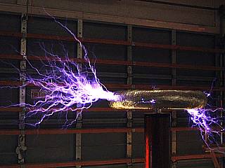
In this picture, streamers approaching 3 feet in length eminate from a rough area of aluminum on my 4x22 inch top-load torus when running my big Tesla coil at near full power. Note that streamers are also in the background as this shot is a 3-second exposure on a Fuji digital camera. |
HTML File "tcpart6.htm" - Developed By Chris Collura
To Return To The HOME Page Of This Site Click The "INDEX.HTM" Link Here!