
| This area shows the construction and testing of a new half-wave (dual) Tesla coil. This type of coil has two secondaries driven by a single tank circuit. The design shown here is a small and rather in-efficient dual coil constructed from scrap parts for basic purposes. This area shows the functioning Tesla coil being tested as well as some other minor improvements being made. The tesla coil project is aimed mainly at the scientific and Tesla coiler community. I intend to use my Tesla coil for lightning demonstrations and entertainment. Note - This page may take a while to load on some SLOWER connections! |
This section shows another different type of Tesla coil design called a half-wave or "twin" Tesla coil. Basically this type is two primaries and secondaries with the primaries wound 180 degrees out of phase in a series fashion. A single tank circuit capacitor and spark gap drives both opposing primaries and a split phase output develops on each secondary top terminal with the RF ground acting as a "center tap". My dual coil was made entirely from scrap material that was left over after building the main single Tesla coil. Instead of throwing it away, I decided to build a small table-top dual Tesla coil. The self-contained system is built in a wood and plexiglass box about 6 inches high, 6 inches wide, and about 16 inches long. The HV power is provided by the same small 10 kV, 23 mA oil burner transformer used in earlier experiments. It was unpotted from its tar case, placed in its own compartment, and sealed in wax (from old candles melted down) becoming and integral part of the coil base unit. The tank circuit is two 30 kV, 0.0025 uF doorknob type capacitors in parallel (0.005 uF total). A MMC of 32 10 kV rated capacitors (0.008 uF total) sealed in wax did not work too well so the doorknobs were used. The series spark gap is a linear static gap (RQ type) quenched with a 12 VDC fan. The spark gap has 4 stainless steel 3/4 inch by 3 inch electrodes giving 3 gaps. The spark gap is series connected through the opposing solenoid-type primary windings of about 10 turns of 1/4 inch copper tubing. The primary supports are made with small plastic boxes and plastic wire-ties and also reduce the risk accidental contacts with the primary coils. The secondary forms are about 500 turns of close-wound #22 magnet wire on a 1 inch by 12 inch thin clear polycarbonate tube. PVC connectors are at each end of the secondaries, with the top terminal at one end and RF ground connections at the other. The shared RF ground is connected to a screw that sticks out of the top of the dual Tesla coil base. A screw terminal is also at the top terminal of each secondary coil. Urethane varnish was used to seal the secondaries.
Notes - This dual Tesla coil was NOT designed for maximum spark length. The approach was to build such a device from scrap meterials that otherwise would have been thrown away! This table-top low power unit only produces a spark length of about three inches without any top loads on each secondary. It is mainly used for demonstration of the Tesla coil concept in a less-dangerous package. The system also resonates in the mHZ range, and considerable RF energy is produced by the unit when operating. The "wireless" light bulb trick works very well with this coil design despite the small sparks.
|
The diagram above is the schematic for my dual Tesla coil design. The dual coil is a half-lambda, or "twin" Tesla coil constructed from spare parts left over from the original Tesla coil trials. AC power is 120 Volts and enters via a main switch and 750 Watt dimmer switch. The dimmer output is fed to an oil burner ignition transformer which produces 10,000 volts at 23 mA. The main switch supplys the dimmer and also powers the spark gap quench fan. The quench fan is a 12 VDC fan with its own small DC power supply connected to the main switch before the dimmer. Parallel-connected to the output of the OBIT is a 0.005 uF tank capacitor (two 2500 pf doorknob capacitors in parallel). The spark gap is a small linear (modified RQ design) with three gaps between four stainless steel 3/4 inch by 3 inch tube electrodes. Series connected to the spark gap are two solenoid type turns of the two primary coils, each tapped at 10 turns. Each of the primary coils are wound in opposite directions to produce a 180 degree double-phase output on each secondary, which is about 500 turns of #22 magnet wire wound in the same direction. The base of each primary is connected to the dedicated RF ground. No mains ground connection is used in this design, just a dedicated RF ground. |
|
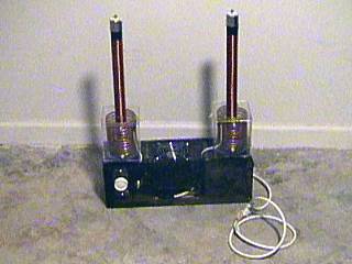
The finished dual Tesla "table top" coil is pictured here. This unit was constructed using only scrap parts and left-overs after designing the original "single" Tesla coil. The dual coil uses primary coils wound in opposing directions (example: first one is clockwise, the second is counter-clockwise) relative to the flow of electricity. This causes the output at the top of each secondary to be 180 degrees out of phase. The entire unit is self-contained and can operate on a table top. The front panel is lexan plexi-glass and has a main on/off switch to control the entire unit and a dimmer switch for the high voltage components. Each secondary is about a foot high and a little over an inch in diameter. Each primary solenoid type coil 1/4 inch copper tune is enclosed in a clear plastic box for safety and coil support. This device is very low power and produces a maximum spark of only a few inches without the top loads as shown here, however, it does produce a lot of RF, since it resonates over 1 Mhz. Fluorescent tubes light up if within a foot or two of the top terminals of the secondaries. |
|
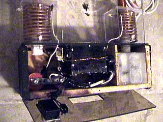
Here is a view of the inside of the base of my dual Tesla coil while I was making final adjustments to the unit. In this picture, we can see the two opposite-winded primary coils (vertical solenoid type) enclosed in plastic cases. The cases not only support the 1/4 copper tube coils, but add an extra margin of safety the the coil operator by reducing the danger of an inadvertant contact with the primary circuit. The secondary supports are two PVC couplings, the white "nut" to the left, that mate with the clear polycarbonate plastic 1 inch by 12 inch secondaries. The two parallel doorknob capacitors can be seen in the lower left side of the box. The modified linear RQ spark gap and fan is in the center of the unit. Note the air intake hole in the cover plate (bottom of picture) and dimmer / main switch controls just to the left. The main oil burner transformer is to the far right of the box, and is sealed in wax in its own integral compartment. Spark gap exhaust is blown up and out through the top of the unit in the center. On the left side of the spark gap is the fan motor power supply, which is 12 V DC ... Sure, this is all scrap parts! |
|
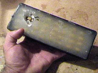
Here is my second attempt at an MMC array using the same 10 KV capacitors each rated at 0.01 uF as in the first Tesla coil attempt. Here, the MMC was a set of 32 capacitors arranged as 16 prallel rows of 2 capacitors in series for a rating of 0.008 uF at 20 KV. The entire unit was placed in a Radio Shack "project case" with terminal screws at each end for the final connections. The entire MMC array was covered with melted hot wax and allowed to harden. After about 5 to 10 minutes of operation, the dual Tesla coil suddenly went silent, and this is what I pulled out of the unit. A carbonized, melted hole in the wax with a failed capacitor inside. The RF heating melted the wax causing an air bubble and eventually a flash over which carbonized the wax making it conductive and shorting the unit. (Should I have used tar or transformer oil)? The MMC was replaced with two of my "tried and true" 30 KV doorknob caps rated at 0.0025 uF each. |
|
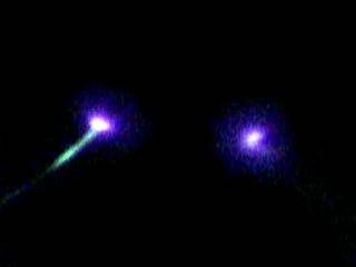
This picture shows the corona effect at the end of two stiff wires between the two top terminals of the dual Tesla coil's secondaries near full power. The wire gap is about four inches wide. The purple / bluish glow is a corona breakout and is also called "Saint Elmos Fire". |
|
The dual Tesla coil is capeable of producing a spark a little over an inch in length from a single secondary terminal to a ground wire. This is not a very powerful, and not a very efficient coil, but it serves well for demonstration purposes, and was constructed from "leftovers" from contruction of my first Tesla coil. Note that this small spark is being drawn from the top terminal without a top load or toroid. In this configuration, the coil produces a lot of RF radiation. |
|
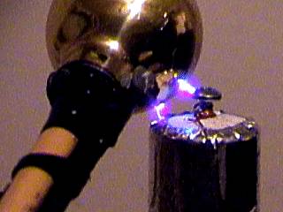
This picture was taken in the dark with the dual Tesla coil running near full output and a spark being drawn from one secondary terminal with a discharge wand connected to the other terminal. No top loads are on either terminal, and we can draw a 2 to 3 inch power arc between the two. |
|
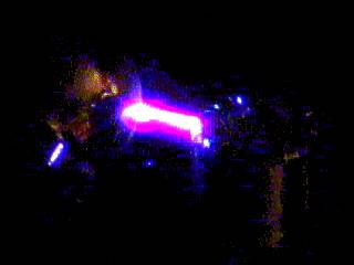
When a discharge electrode is connected to one secondary terminal and brought near the top of the other, arcing and corona occurs. In this picture, the arc is being drawn to the insulation / shield of a coaxial cable just below the discharge "doorknob" at the end of the discharge wand. Since this incorporates capacitance due to the insulating sheith of the cable, a cool effect of many little discharges covers the entire end of the discharger. Note that there is no top load on the terminal. This eventually burned a small hole in the rubber coating of the cable. A personal computer left on in another room about 50 feet away also locked up and needed to be re-booted after this test was done. RF energy and computers don't get along! |
|
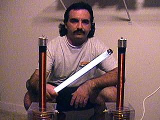
This is a picture of myself standing about three feet behind the dual Tesla coil near full power. With the top load off each secondary, a lot of RF energy is radiated through space and lights up a fluorescent tube in my hands, without any physical contact. The light is no less than a foot away from the unit. Again, Nikola Tesla's concept of "wireless transmission of electricity" becomes apparent. |
|
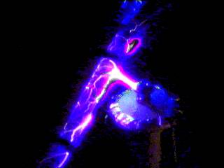
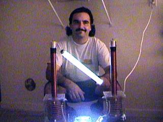
Here is another picture of myself holding a fluorescent light while standing in low lighting a few feet behind my dual Tesla coil at full-power. The tube lights up brightly when held a foot or two away from the coil secondary. Note the bright actinic-blue light in the lower portion of the picture from the spark gap. |
HTML File "tcpart5.htm" - Developed By Chris Collura
To Return To The HOME Page Of This Site Click The "INDEX.HTM" Link Here!