| This area shows my first attempt at building a Tesla coil. The Tesla coil project is aimed mainly at the scientific and Tesla coiler community. I intend to use my Tesla coil for lightning demonstrations and entertainment. Note - This page may take a while to load on some SLOWER connections! |
Below are the construction details of my first tesla coil. The project uses a 10,000 volt at 23 mA oil burner ignition transfomer driving a primary made from 18 turns of #8 copper. The secondary is a 3.5 inch PVC with about 1000 windings of #22 magnet wire. The spark gap is a Richard Quick type static gap in a 4 inch PVC enclosure vented via a 12 volt muffin fan from a PC power supply. This is a first attempt at this type of project with the main goal as functionality, rather than spark size. From such a "weak" HV power source (23 mA at 10,000 v), the finished coil produced 6 inch sparks before the plate capacitors failed due to flashover.
Lessons learned - Plate capacitors using plastic plates such as plexiglass or polycarbonate are subject to frequent flashovers and failures. Try to use MMC (Multiple Miniature Capacitors) arrays where small "snubber" capacitors can be series / parallel connected to get the proper ratings. Use thicker wire for your primary coil and try not to paint over it :-)
|
The diagram above is the schematic for my first Tesla coil. The AC input runs through a 120 VAC line filter (from a PC power supply plug) to a 10,000 volt 23 mA oil burner ignition transformer. The primary circuit of the tesla coil assembly is series connected with the 0.0061 uF tank capacitor. The Richard Quick type spark gap is parallel connected in the circuit and includes a larger safety gap. The secondary is connected to RF ground at one end (not the mains ground, ofcourse) and the other end is the output HV terminal for the coil. The RQ spark gap fan is powered by a small 12 VDC cooling fan running off a small 12 VAC step-down transformer and a rectifier to power the fan. |
|
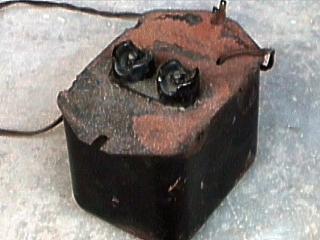
This is a picture of the 230 VA oil burner ignition transformer (OBT) for my coil. It puts out about 10,000 volts at 23 milliamps. The two glass insulated terminals on the flange side of the transformer is the high voltage output. |
|
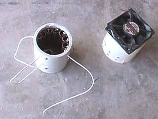
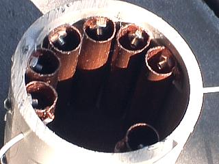
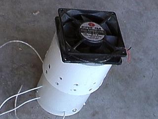
This is the Richard Quick type spark gap I used for my tesla coil. The gap contains six 1/2 inch copper pipes about 3 inches long inside a 4 inch PVC pipe section. A seventh 3 inch copper electrode will serve as the spark safety gap for the power supply HV transformer. The gap assembly is to the left and the cooling fan assembly if to the right. The cooling unit is a 12 vold muffin type fan from a PC power supply glued atom a PVC end cap with PVC cement. |
|
A closeup of the Richard Quick type spark gap assembly. The six 1/2 inch copper tube electrodes are across the top. There is about 1/16 inch clearance between each 3 inch copper tube constituting a total spark gap of about 3/8 inch. The single tube electrode on the bottom is the spark safety gap to protect the HV transformer. |
|
When assembled, the Richard Quick gap and quench / cooling fan assemblies will look something like this. The end cap still needs to be trimmed in this picture. Note that the fan is far from the electrodes in the gap assembly to avoid the risk of any unwanted arcing. The lead wires to the spark gaps can also be seen in this picture. |
|
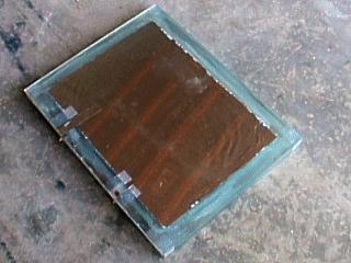
This is a picture of the high density plastic (HPDE) plate capacitor used in this project. There is a total of 8 metal aluminum foil plates stacked with 9 sheets of 1/8 inch thick polyethelyne. Each plate is roughly 10 by 8 inches and yields a capacitance of about 6.1 pF (0.0061 uF). The two terminals for the capacitor are on the left side of this picture. |
|
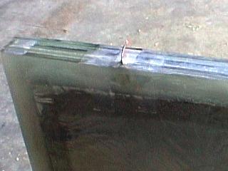
This is a closeup of the HDPE plate capacitor showing the layers of 1/8 inch thick plastic plates separating the aluminum foil plates inside. The entire unit is sealed with PVC cement and at least and inch clearance is left on each side between the foil edge and dielectric edge to prevent unwanted corona or arc discharge. The interleaved plates connect in parallel to the terminals. One of the wire terminals also can be seen in this picture. |
|
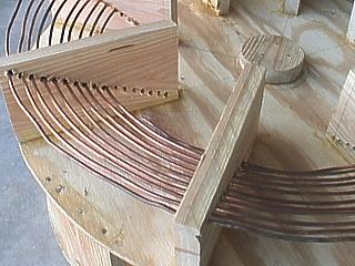
This picture shows a closeup of the unfinished primary coil and assembly. The primary coil is made from #8 solid bare copper wire mounted through a 26.5 degree inverted cone formed from drilled plywood sections. The winding got very diffucult every seven turns or so and needed to be done in sections. The thick copper wire is very easy to solder if needed. The primary coil spacing is roughly 1/2 inch. |
|
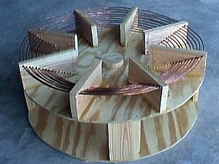
This is the unfinished primary coil as well as the primary coil support structure and base for my tesla coil. The tables are a 24 inch diameter 3/8 inch plywood with the supports made from sections of 1 inch by 4 inch wood stock. The center hub will serve as the mount for the secondary coil. The primary coil is only half finished in this picture and the strike rail has not yet been installed. The bottom of the base has space for the RQ spark gap, power supply, and plate capacitor. |
|
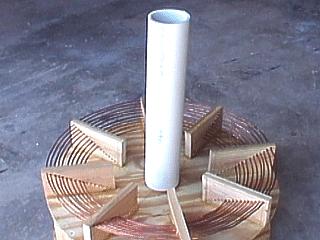
The unfinished base and primary coil for my tesla coil with the unwound secondary form sitting on the "hub" mount. The secondary form is a 4 inch PVC tube and will be treated with urethane sealant and wound with #22 magnet wire. |
|
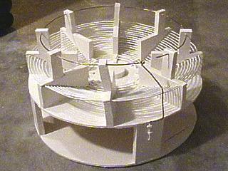
This is the finished base and primary assembly. It has been painted white and the strike rail / discharge wand terminal attached. The finished primary coil has 20 turns of solid AWG 8 bare copper ground wire and is a inverted cone of about 25 degrees. The primary will be tapped at about 12 or 15 turns. |
|
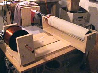
For winding the secondary coil, I constructed this simply lathe from scrap lumber. Each end has a "C" shaped section, the one on the left hold the spool of magnet wire supported by a loose copper pipe. The section on the left holds the PVC form to be wound. The form is supported by two wood wedges in each end with bolts coming out. In one of these bolts, a drill is chucked so the lathe can be turned. The drill can be seen in the background, and is supported by vice grips to the level surface the lathe is sitting on. |
|
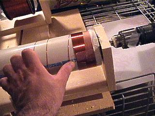
Here is a closeup of the winding of the secondary coil on its PVC form using the winding lathe. The variable-speed Milwaukee drill is to the right, turning the form via a bolt. As the form turns it takes up the magnet wire. You can easily stop and start the drill as you hand-guide the magnet wire to its best. I used scotch tape to hold the finished section of the winding until the process is completed. |
|
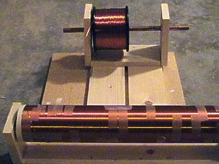
Here is a picture of the secondary fully wound and still on the lathe. Note the pieces of scotch tape I used to hold the windings tight as I worked. The finished secondary has about 900 to 1000 turns of AWG 22 magnet wire, and is roughly 4 inches in diameter and about 24 inches in length. |
|
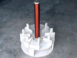
The finished secondary coil, a 4 inch by 24 inch winding of 900 to 1000 turns of #22 magnet wire, sits on top of the base / primary assembly. The top electrode is a thin sheet of aluminum foil hooked up to the last turn of the magnet wire. This will be topped with a metallic end-cap and a detachable toroid top-load. The RF ground (first winding) is attached to the same circuit as the strike rail and discharge wand - NEVER attach this to your AC ground! |
|
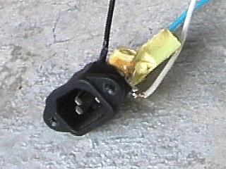
A PC power supply plug was used for easy connection of the tesla coil to AC power. Note the small capacitors and chokes that make up a line noise filter for the power input to the coil. |
|
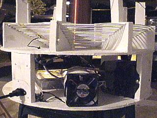
The completed base with components installed for the tesla coil. The RQ spark gap with cooling fan can easily be seen in the front of the unit. The oil burner ignition transformer is mounted on the right support stud. The plate capacitor is behind all components and is anchored to the bottom plate. Note the PC power supply plug on the support stud to the left. The PC cooling fan is also powered by a 12 volt power supply behind the support stud to the left. |

|
This is a picture of the toroid I will use for my tesla coil. It is constructed from 4 inch aluminum ventilation ducting and can be easily fitted to the top terminal on my coil. It can easily be fitted and removed. |
|
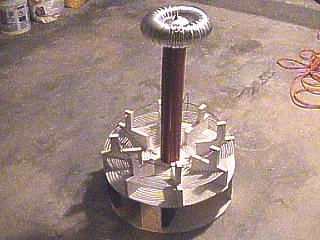
This is the finished tesla coil. It stands about 3 feet high and produces sparks up to 6 inches in length. This is rather small due to the limited power from the oil burner transformer. |
|
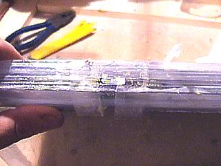
In only a few seconds of operation, the plate capacitor shorted out - ARGH!! Nearly 40 bucks worth of plexiglass and assembly gone! After removing the capacitor unit, the culprit was between the dielectric layers near each terminal. The corona, which made the entire capacitor glow an eerie blue in total darkness when energized, eventually flashed over and carbonized the HDPE plastic. In this picture, the brown streak and melting is obvious. A new capacitor design is being considered. |
HTML File "tcpart1.htm" - Developed By Chris Collura
To Return To The HOME Page Of This Site Click The "INDEX.HTM" Link Here!